S1 series standard inverter
-9-
R
S
T
U
V
W
(+)
(-)
PE PE
PB
DC reactor
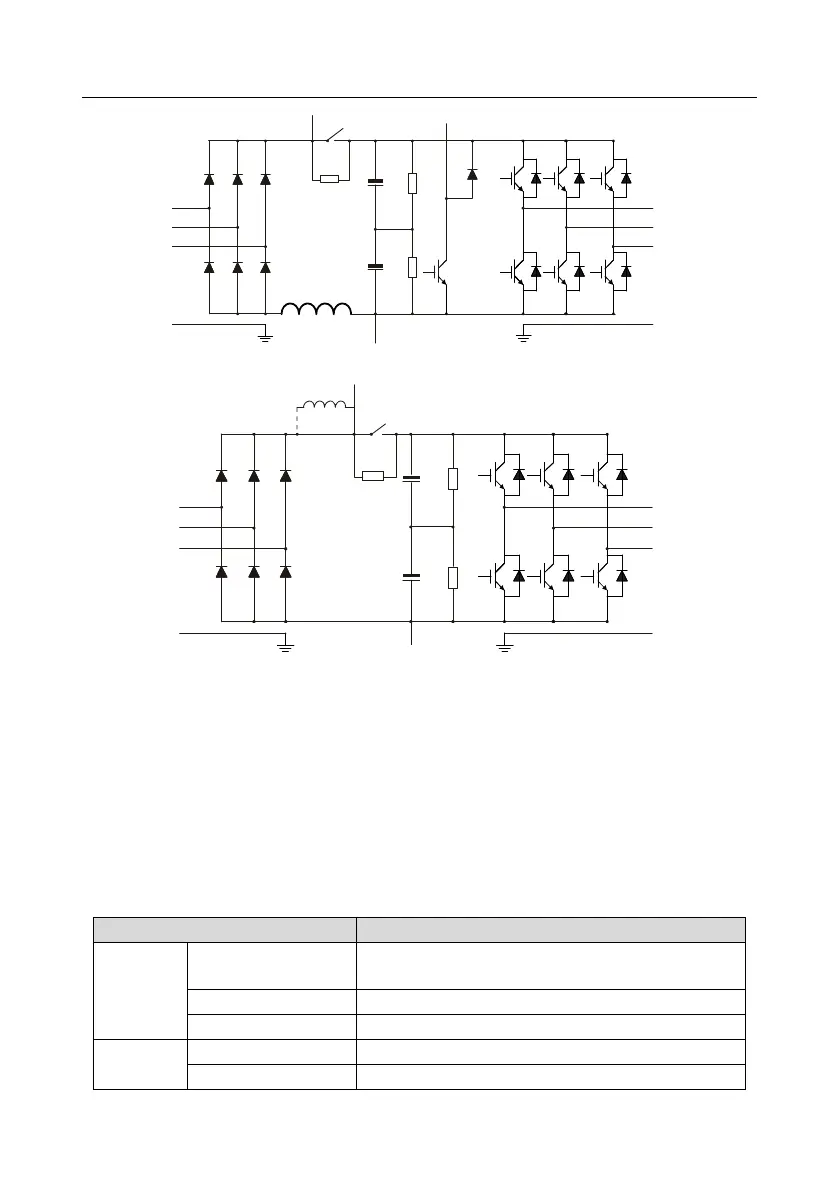
Fig 3.4 400V (18.5kW–110kW) main circuit diagram
R
S
T
U
V
W
(+)
(-)
DC reactor
P1
PE PE
Fig 3.5 400V (132kW and above) main circuit diagram
Note:
1. 132kW and above inverters can be connected to external DC reactors. Before connection, it is
required to take off the copper bar between P1 and (+). 132kW and above inverters can be
connected to external brake unit. DC reactors and brake units are optional parts.
2. 18.5kW–110kW inverters are equipped with built-in DC reactor.
3. 37kW and below models carry built-in brake units, 45kW–55kW supports built-in brake unit.
75kW–400kW supports external brake unit. The models that carry built-in brake unit can also be
connected to external brake resistor. The brake resistor is optional part.
3.3 Product specification
AC 1PH 220V (-15%)–240V (+10%) rated voltage: 230V
AC 3PH 380V (-15%)–440V (+10%) rated voltage: 400V
50Hz or 60Hz, allowable range: 47–63Hz
 Loading...


