2.11 Control circuit wiring section
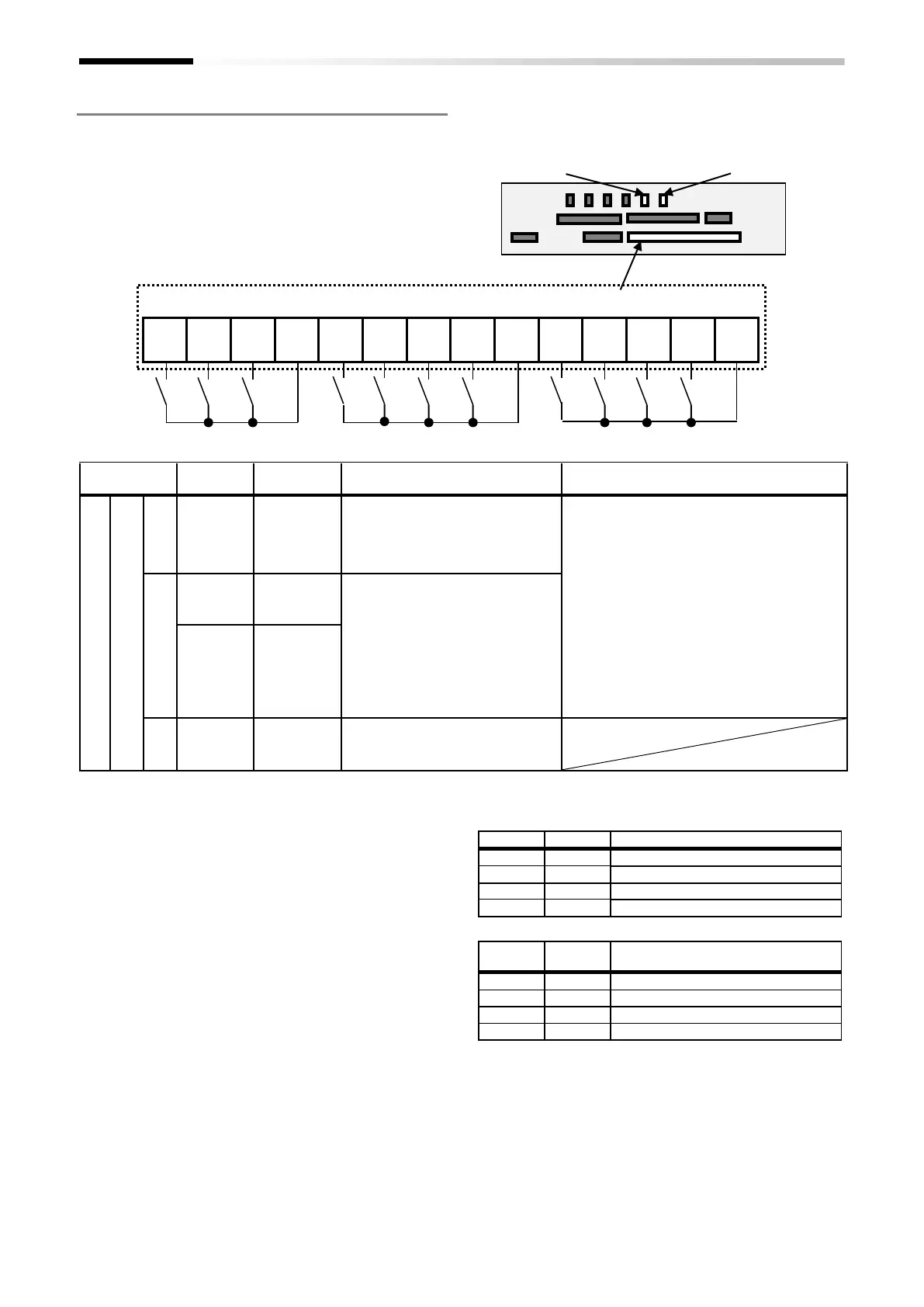
■ Input terminals
• All COMs have the same electric potential.
• Change SW5 to external power supply (EX) to connect
the power supply between Input terminals 1 to 9, A or
B, and COM.
• Sink or source logic of the input terminal is switched by
SW6.
(Wiring example)
• [] it means factory default settings.
■ Terminal’s default function ([symbol: setting No.])
[RS:028]Reset
• Reset at every trip.
[SCHG:015]Command source change
• Change to the main speed command [AA101](OFF) or
sub-speed command[AA102](ON).
[JG:029]Jogging
• [JG]ON runs the inverter at a frequency of [AG-20].
[FRS:032]Free-run stop
• [FRS]ON sets the motor in a free-run state.
[2CH:031]Two-step acceleration/deceleration
• [2CH]ON enables acceleration/deceleration
time-2[AC124][AC126].
[EXT:033]External trip
• [EXT]ON issues Trip[Er012].
[FW:001]Forward rotation and [RV:002]Reverse rotation
Forward rotation RUN command.
Reverse rotation RUN command.
No command (inconsistent logic)
[CF1:003]Multispeed-1 and [CF2:004]Multispeed-2 commands
The set frequency source is enabled.
The frequency source of [Ab-11] is enabled.
The frequency source of [Ab-12] is enabled.
The frequency source of [Ab-13] is enabled.
*) Setting CF3 and 4 allows you to set up to 16-speed.
[USP:034]Unattended start protection
• In a [USP]ON state, if an RUN command has been input
before the power supply is ON, Trip[E013] is issued.
Intelligent input terminal
s
9, 8,
7, 6,
5, 4,
3, 2,
1
Each terminal can select input
terminal functions by parameter
setting.
Switch the SINK / SRC of SW6 to
select the sink logic and source logic.
• Max. allowable voltage 27 VDC
• Load current 5.6 mA (at 27 VDC)
Voltage between each input and the COM
terminal:
When using an external power supply:
• ON voltage Min.18 VDC
• OFF voltage Max.3 VDC
When using the internal power supply:
• ON voltage Max.3 VDC
• OFF voltage Min.18 VDC
• Maximum 32 kbps pulse input
( When terminal A and B function is
pulse train input A/B )
When [CA-90] is set to 00, A and B
terminals can be used as input
terminals.
Each terminal can select input
terminal functions by parameter
setting.
When [CA-90] is not set to 00,
they are used as terminals for
pulse train input.
The maximum input pulse is 32kpps
This is a common terminal for digital
input terminals (1,2,3,4,5,6,7,8,9,A and
B). Three COM terminals are available.
 Loading...


