--- 9 ---
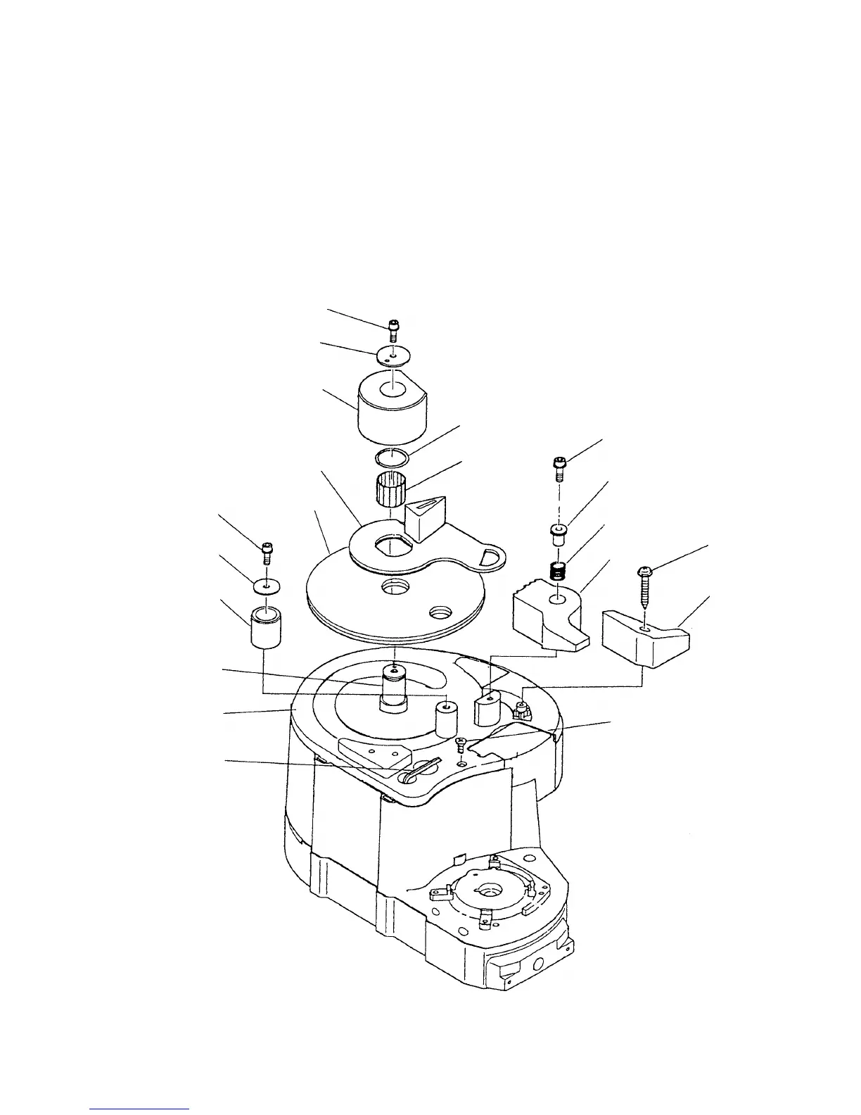
(3) Disassembly of the bending unit (Fig. 10)
(a) Remove the Nylock Bolt (W/Flange) M5 x 16 [6], Washer (A) [34] and Center Roller (D62) Set [35].
Remove the O-ring [9] from the Cam Shaft [12] then remove the Needle Bearing (D22) [36].
(b) Remove the Nylock Bolt (W/Flange) M5 x 25 [37], Sleeve (G) [39], Spring (G) [40] and Guide (D62) [41].
The Center Plate [1] can then be removed.
(c) Remove the Tapping Screw (W/Flange) D4 x 20 (Black) [42] and Lever (B) [43].
(d) Remove the Turn Table [2], Washer [7] and Roller (B) [8].
(e) Remove the Turn Table [2], Hex. Bar Wrench 4 mm [33] and three Nylock Flat Hd. Screws M4 x 12 [3] to
remove the Cam Cover [4].
Fig. 10
[6]
[35]
[34]
[4]
[3]
[8]
[12]
[37]
[40]
[39]
[6]
[41]
[1]
[7]
[2]
[33]
[43]
[42]
[36]
[9]
 Loading...