Do you have a question about the Hitachi Z-HD5000 and is the answer not in the manual?
Tests and findings regarding FCC Rules for Class A digital devices, designed for commercial environments.
Compliance with Canadian radio noise emission limits for digital apparatus.
Details on the guarantee period, exclusions, repair policies, and liability limitations.
Covers viewfinder lens hazard, power supply, disassembly, foreign objects, and location selection.
Guidelines for connecting/disconnecting cables, transporting, using tripods, and cleaning.
Explains innate CCD phenomena like Smear and Fixed pattern, not malfunctions.
Precautions for handling fiber-optic patch cables to maintain signal quality.
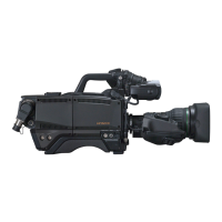
Identifies accessory shoe, viewfinder lock screw, lens mount, and shoulder pad.
Details the viewfinder attachment and shoulder belt hook.
Describes the CALL button, POWER switch, and Filter knob.
Details connectors for the viewfinder and the Camera Control Unit (CCU).
Identifies HD-SDI outputs, remote control, and prompt connectors.
Describes the RET button, AC230V OUT, and shoulder belt hook.
Details the MIC connector and the LENS connector.
Describes the SHUTTER switch and AUTO W/B BAL switch.
Explains intercom controls and the MENU SELECT knob/button.
Covers POWER LED, CS-2, FILTER, ECC, and CS-1/CHECK switches.
Details GAIN, OUTPUT/AUTO KNEE, and WHITE BAL switches.
Describes the MENU button and the POWER switch.
Describes the CS switch for custom functions.
Explains TALLY ON/OFF switch and RED/GREEN TALLY LED.
Details switches for selecting return video signals (RET1/2).
Manages intercom volume, talk function, and mic modes.
Selects PD or ENG input for external intercom system.
Describes SCRIPT connector and RET CONT connector.
Details DC IN connector, MIC SEL switch, MIC connectors and MIC power.
Identifies the HD-SDI 1 output connector.
Step-by-step guide for mounting a lens onto the camera.
Notes on required adjustments like flange back and white shading.
Detailed steps for adjusting the lens flange back for precise focus.
Additional notes and references for lens adjustment.
Steps for optimizing camera vertical coloration after lens replacement.
Instructions for performing white shading via the maintenance menu.
Notes on limitations and potential coloration after adjustment.
Steps for aligning and securing the camera adapter.
Warning to tighten screws fully to prevent adapter wobble.
Steps for attaching the camera to a tripod using the adapter.
Instructions for removing the camera from the tripod adapter.
Warnings regarding weight capacity and screw hole usage.
Steps for attaching the 5-inch viewfinder using the adapter.
Instructions for inserting and securing the viewfinder into the slot.
Steps for disconnecting and removing the viewfinder and adapter.
Steps for mounting the viewfinder onto the camera body.
Adjusting horizontal, vertical, and depth positions for comfort.
Adjusting the vertical angle of the eyepiece for comfortable viewing.
Fine-tuning focus for individual preference using the visibility ring.
Controls for Brightness, Contrast, and Peaking on the viewfinder screen.
Safety warnings regarding sun exposure through the eyepiece lens.
Describes the meaning of TALLY, EXT, and MODE LEDs in the viewfinder.
Explains status messages shown on the viewfinder screen.
Guidance on selecting optical filters for correct white balance.
Procedure for adjusting white balance, including steps and conditions.
Lists potential error messages during auto white balance and their corrections.
Procedure for adjusting black balance, including steps and conditions.
Lists potential error messages during auto black balance and their corrections.
Procedure for auto-adjusting parameters using a gray scale chart.
Describes selectable electronic shutter modes and their applications.
Procedure for changing shutter speed and mode.
Instructions for using LOCK SCAN mode to avoid monitor flicker.
Covers handling, insertion, removal, notes, and cautions for SD memory cards.
Details loading, saving, clearing data, and viewing results.
Explains status flowcharts, error indications, and handling faulty cards.
Describes menu methods, operation, navigation, structure, and displays.
Details VF structure, markers, display settings, and related controls.
Covers COLOR and DETAIL menu structures and adjustment sub-menus.
Covers MAINTENANCE, SYSTEM, TIME/DATE, and OTHERS menus.
Covers CHECK, RLAC, FILE, CUSTOM SW, Auto Setup, Picture Quality, Skin Tone.
Technical specifications for the Z-HD5000 camera head.
Specifications for the CA-HF1000 and CX-HD1000 adapters.
Details for 2-inch, 5-inch, 7-inch, and 9-inch viewfinders.
Diagrams showing the dimensions of camera heads and viewfinders.
Dimensional drawing for the VF-L90HD viewfinder.
Dimensional drawing for the VF-HD500 viewfinder.
Dimensional drawing for the VF HDF-700 viewfinder.
Diagram illustrating system connections for fiber and triax setups.
Explanation of the POWER switch positions (EXT, CCU).
Pin configurations for LENS, REMOTE, DC IN, and MIC connectors.
Pin details for Intercom, Script, and RET CONT connectors.
Describes AC230V OUT connector and safety warning.
Location of the prompter power connector on the Camera Adaptor CA-HF1000.
Details on parts, Hitachi code, pinout, and connection notes.