7
/
18
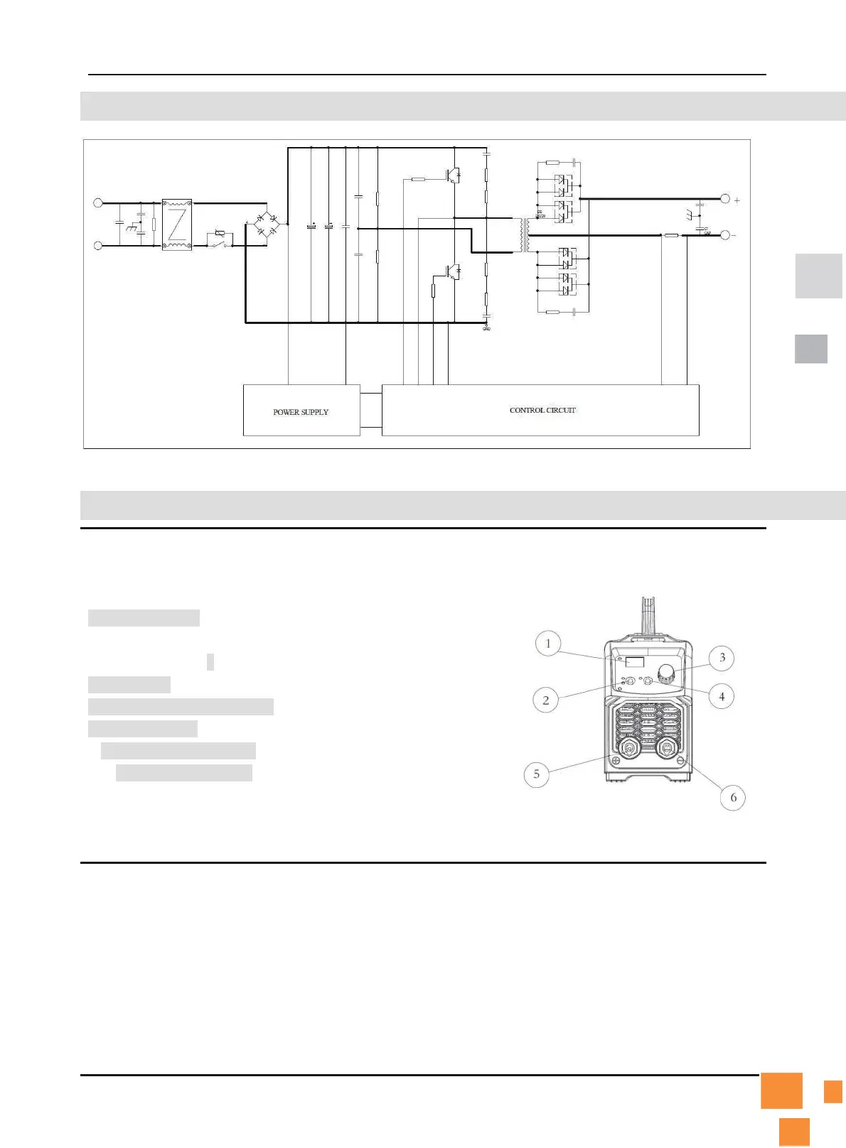
8. ELECTRICAL SCHEMATIC DIAGRAM
Fi
g. 1
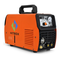
9. OPERATION CONTROL AND DESCRIPTION
1.Display meter: To show welding current normally. Showing
“E-1” indicates Over current protection, “E-3” indicates over
heating protection
2.TIG/MMA: To switch Lift-TIG/MMA welding mode
3. Welding current knob: To adjust the output current.
4. VRD switch: To turn ON/OFF VRD function
5.
"+" output terminal: To connect the electrode holder.
6.
"-" output terminal: To connect the work clamp.
Fig. 2