Do you have a question about the HKC HM04 and is the answer not in the manual?
Explains the manual's objective for installing, operating, and maintaining HM actuators.
Lists the key sections and topics covered within the installation and operating manual.
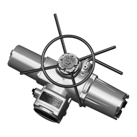
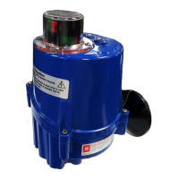
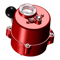
Identifies and illustrates the external components of the standard HM series electric actuators.
Details critical safety precautions to reduce risks of personal injury and equipment damage during operation.
Describes how to identify the actuator model using its nameplate information.
Lists the specific data and labels found on the actuator's nameplate for identification.
Provides steps for inspecting the actuator for damage and verifying specifications after delivery.
Gives guidelines for proper storage conditions to maintain actuator integrity before installation.
Provides a general overview of the HM series electric actuators and their applications.
Presents performance specifications including RPM and torque for various HM series models.
Detailed table of torque values for AC 3-phase HM series actuators at different RPMs.
Detailed table of torque values for AC 1-phase HM series actuators at different RPMs.
Torque specifications for solid-state design HM actuators in 3-phase and 1-phase configurations.
Provides mechanical specifications like flange size, weight, and stem acceptance diameter.
Comprehensive technical specifications for standard HM series actuators, including enclosure and power supply.
Details optional features and their technical specifications for HM series actuators.
Explains duty cycle ratings (S2, S4) and their implications for actuator operation.
Describes the procedure for using the manual override hand wheel and declutching the actuator.
Information regarding the permanent lubrication of the gear train and its maintenance implications.
Illustrates and labels the main internal components of the standard HM series actuators.
Critical checks and verifications required before installing the actuator in general or explosive atmospheres.
Guidance on the correct procedures and considerations for mounting the actuator onto a valve.
Specific details and dimensions for actuator mounting according to ISO5211 and ISO5210 standards.
Provides flange size information and corresponding torque/thrust values for mounting bases.
Step-by-step illustration for disassembling the mounting base from the actuator.
Instructions for disassembling the drive bush from the thrust base, including parts and assembly.
Instructions for disassembling the drive bush from a non-thrust base configuration.
Essential steps for making electrical connections and performing preliminary tests before operation.
Outlines recommended maintenance intervals and procedures for HM actuators.
Lists the essential tools required for performing maintenance on HM series actuators.
Provides common causes and solutions for when the actuator fails to respond to commands.
Addresses issues where the actuator has power but does not perform its intended function.
Offers troubleshooting steps for erratic actuator behavior and operational anomalies.
Presents the detailed wiring diagram for standard HM series 3-phase electric actuators.
Wiring diagram specific to HM series 3-phase actuators equipped with Current Position Transmitter (CPT).
Wiring diagram for HM series 3-phase actuators featuring Proportional Control Unit (PCU).
Explains the coding system used for identifying and ordering HM series electric actuators.
| Brand | HKC |
|---|---|
| Model | HM04 |
| Category | Controller |
| Language | English |