EasyManua.ls Logo

HKC HQ-015 - User Manual

HKC HQ-015
26 pages
Print Icon
To Next Page IconTo Next Page
Loading...
HQ Series Quarter-turn Electric Actuator
Installation Operation& Maintenance Manual
Doc No. : HumG-HQ-21 Rev2 Page 1 / 26 Valve Automation Leader, HKC
HQ Series Quarter-turn Electric Actuator
Installation, Operation & Maintenance Manual
Address : 26, Emtibeui 28-ro, Siheung-si, Gyeonggi-do, (15119) Republic of Korea
Tel : +82-31-488-8266, Fax : +82-31-488-8269, Home page : www.hkcon.co.kr, email : hkcon@hkcon.co.kr
Question and Answer IconNeed help?

Do you have a question about the HKC HQ-015 and is the answer not in the manual?

Summary

Manual Introduction and Safety Notices

General Safety Precautions

Outlines precautions for reducing risk of personal injury and equipment damage.

Actuator Installation Procedures

Pre-Installation Checks

Ensuring correct model, torque, speed, voltage, and duty cycle before installation.

Installation in Explosive Atmospheres

Safety precautions and requirements for installing actuators in potentially explosive environments.

Actuator Mounting Guidelines

Instructions on how to mount the actuator, including alignment and securing methods.

Installation Adjustments and Settings

Limit and Torque Switch Adjustment

Procedures for setting limit switches and information on torque switches.

Mechanical Travel Stop Adjustment

Procedure for adjusting the mechanical travel stops for open and close positions.

Signal Feedback and Calibration

Potentiometer Setting and Calibration

Guide for re-calibrating the potentiometer if required, including resistance measurements.

CPT and PCU Configuration

CPT Zero and Span Calibration

Step-by-step instructions for calibrating the Zero and Span settings of the CPT.

Proportional Control Unit (PCU)

Overview of the PCU, including its function and types (AC/DC).

PCU Specifications and Operation

PCU Advanced Settings

Deadband Setting

Defines deadband and provides adjustable setting ranges for PCU units.

Deadtime Setting

Explains deadtime, its purpose for preventing noise, and adjustable setting ranges.

PCU Operational Modes

Fail-Safe Operation Modes

Configuration for Fail Close, Fail Open, and Fail Stop modes using DIP switches.

PCU Signal Adjustment

Random Command Signal Setting

Procedure for setting Zero and Span signals for the actuator using DIP switches.

PCU Manual Operation and LED Status

AC;DC Multi-board and Communication

Optional Communication Protocols

Communication Protocols and Wiring

Electrical Connections and Preliminary Test

Guidelines for making electrical connections and performing preliminary tests before operation.

Wiring and Testing Procedures

Connecting wires, testing motor rotation, and verifying limit switch function.

Maintenance Procedures

Routine Maintenance

Guidelines for regular maintenance, including safety warnings and interval recommendations.

Troubleshooting Common Issues

Actuator Not Responding

Troubleshooting steps for when the actuator shows no response to commands.

Actuator Supplied with Power, Not Operating

Steps to diagnose why the actuator has power but fails to operate.

Troubleshooting and Maintenance Tips

Erratic Actuator Operation

Troubleshooting steps for when the actuator operates erratically or inconsistently.

Safety Defect Reporting

Procedure for addressing detected defects that may affect safety during maintenance.

Wiring Diagrams

Additional Wiring Diagrams

DC Wiring Diagrams with PCU

Grounding Procedures

Overview

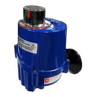
The HKC HQ Series Quarter-turn Electric Actuator is designed for the operation of industrial valves, such as butterfly and ball valves. This manual provides comprehensive instructions for its installation, operation, and maintenance.

Function Description:

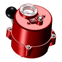
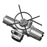
The HQ Series electric actuators provide precise control for quarter-turn valves. They are equipped with a declutchable manual override system, allowing for manual operation in case of power failure or for initial setup. The actuators can be configured for clockwise (standard) or counter-clockwise rotation to close, by adjusting the wiring and PCU board settings.

The actuators feature limit switches to define the fully open and fully closed positions, and torque switches to prevent damage from overload conditions. An optional Current Position Transmitter (CPT) provides a 4-20mA output signal, indicating the current valve position. For more advanced control, a Proportional Control Unit (PCU) is available, offering various input and output signal types, dead time, and dead band settings. Communication protocols like ProfiBus and ModBus are also supported as optional features, enabling remote control and monitoring.

Important Technical Specifications:

  • Torque Output: Ranges from 40 Nm to 8,830 Nm (350 In-Lbs to 78,120 in-Lbs), with 19 models available.
  • Operating Time (90°): Varies by model, e.g., HQ-004 (12/12 sec), HQ-080 (37/31 sec), HQ-900 (117/99 sec).
  • Power Supply: Available in AC (1 phase 50/60 Hz, 3 phase 50/60 Hz) and DC (24V dc, 12V dc).
  • Rated Current: Varies significantly by model and power supply, e.g., HQ-008 (0.5/0.5 A for 220Vac 1ph), HQ-080 (1.1/0.7 A for 440Vac 3ph).
  • Enclosure Rating: Ingress protection IP67, NEMA 4, 4X & 6 (Weatherproof). Optional IP68 (10m / 72hr) for watertight applications.
  • Explosion Proof Options: IECEx, ATEX, CSA, KCs, EAC certified for Ex db IIB T4 Gb and Ex tb IIIC T135°C Db.
  • Ambient Temperature: -20 °C to +60 °C (except on CPT & PCU board, which is -25°C to 80°C).
  • Motor: Squirrel caged induction motor with built-in thermal protection.
  • Switches:
    • Limit Switches: 2 x open/close SPDT, 250 Vac 16A rating.
    • Auxiliary Limit Switches (Optional): 2 x open/close SPDT, 250 Vac 16A rating (except HQ-008/010).
    • Torque Switches: Open/close SPDT, 250Vac 16A Rating (except HQ-008/010).
    • Additional Torque Switches (Optional): 2 x SPDT 250V ac 16A Rating.
  • Travel Angle: 90 degrees +/- 10%.
  • Self-Locking: By means of worm gear.
  • Mechanical Travel Stops: 2 x external adjustable mechanical travel stops.
  • Cable Entries: [2xNPT 3/4", 2xM25 for Ex db, additionally M20, M25 and NPT3/4" with M30 adaptor for Ex tb (by user selection)].
  • Lubrication: Grease moly EP, almost permanently lubricated.
  • External Coating: Dry powder polyester coating, max thickness 2mm for Ex tb application.
  • Duty Cycle: Short-time duty S2 or Intermittent duty S4, as per VDE 0530 / IEC 60034-1. Exceeding rated duty cycle may cause thermal overload.
  • Space Heater: Ceramic housing with thermostat (60°C set temperature) to prevent condensation.
  • Proportional Control Unit (PCU) Specifications:
    • Input Signal: 4~20mA dc, 0~20mA dc, 1~5V dc, 0~5V dc, 2~10V dc, 0~10V dc.
    • Output Signal (feedback): 4~20mA dc, 0~20mA dc, 1~5V dc, 0~5V dc, 2~10V dc, 0~10V dc.
    • Dead Time: 0.2~7.5 sec (16 steps).
    • Dead Band: 0.3~7.5% (AC PCU), 0.4~7.5% (DC PCU) (16 steps).
    • Fault Mode: Fail close, Fail open, Fail stop.
  • Current Position Transmitter (CPT) Specifications:
    • Output Signal: 4~20mA dc.
    • Output Impedance: 7500 max.
    • Position Conversion Accuracy: ±0.5 ~ ±1.5%.
  • ProfiBus Controller (PBC) Specifications:
    • Communication: Profibus communication (RS-485 base).
    • Max. Range: 1000m @ 9.6 ~ 187.5 k Baud.
    • Bit Rate: Up to 12mega.
  • ModBus Controller (MOB) Specifications:
    • Communication: Modbus-RTU (RS-485 communication).
    • Supported Baud Rates: 1200 to 115200.

Usage Features:

  • Easy Mounting: Designed for mounting with the valve shaft pointing vertically upward, but can be mounted in any position. ISO5211 bolt patterns are provided, and the drive bush is removable for machining.
  • Manual Override: A declutchable hand wheel allows for manual operation by pulling the engagement lever.
  • Limit Switch Setting: Simple adjustment of CLOSE and OPEN limit switch cams using a hex wrench.
  • Potentiometer Setting: Factory-calibrated, but can be re-calibrated by rotating the potentiometer gear to achieve desired resistance values.
  • CPT Calibration: Zero and Span dials on the CPT board allow for calibration to achieve 4mA (closed) and 20mA (open) output signals.
  • PCU Configuration: DIP switches on the PCU board enable selection of input signal type, output feedback signal, deadband, deadtime, fail-safe modes (fail close, fail open, fail stop), auto full action, and reverse mode.
  • Auto Setting Function: The PCU board can automatically set the actuator's positions by pushing the ASCAN button, with LED indicators showing the progress.
  • Manual Operation Mode: Allows manual control of the actuator's open and close positions via ZERO and SPAN buttons on the PCU board.
  • LED Display: Provides visual feedback on the actuator's status (Open, Auto, Close, Fault) and error conditions, aiding in troubleshooting.

Maintenance Features:

  • Regular Inspections: Recommended every six months, or more frequently in severe conditions.
  • Visual Checks: Inspect for external damage, proper alignment with the valve, secure wiring, tight screws, and cleanliness of internal electrical devices.
  • Condensation Check: Verify the absence of condensation and proper functioning of the internal heater.
  • Seal Integrity: Check enclosure O-rings for damage and proper seating.
  • Declutch Mechanism Check: Verify proper operation of the manual override.
  • Wiring Diagram: Detailed wiring diagrams are provided for various models and power configurations (1Ph, DC, PCU), facilitating electrical connections and troubleshooting.
  • Troubleshooting Guide: A comprehensive section addresses common issues such as the actuator not responding, operating erratically, or failing to operate despite power supply, with suggested countermeasures.
  • Grounding: Instructions for internal and external grounding connections are provided, emphasizing the importance of proper grounding for safety and performance.
  • Parts Replacement: Emphasizes the use of original spare parts for seals and other components.
  • Explosion Proof Considerations: Specific warnings and instructions for working in potentially explosive atmospheres, including requirements for certified cable glands, blanking elements, and surface cleaning.
  • Cover Bolt Tightening Torque: Specified tightening torques for cover bolts (e.g., M8 x 35: 12.5 Nm, M12 x 55: 42.0 Nm) to ensure proper sealing and safety.

HKC HQ-015 Specifications

General IconGeneral
D-PadYes
Connectivity TechnologyWired
PlatformPC
CompatibilityWindows
ConnectionUSB
VibrationYes
Analog Sticks2

Related product manuals