

C
Cindy WallerAug 2, 2025
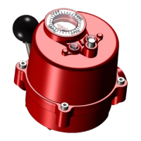
Why is the manual override on my HKC Controller hard to turn?
- FfwilliamsAug 2, 2025
If the HKC Controller's manual override is hard to turn, it could be due to an improperly lubricated valve stem or a valve packing gland that is too tight. In the first case, you should clean out the old grease and replace it with the recommended lubricant. In the second case, loosen the packing gland nuts as necessary.