HQ Series Quarter-turn Electric Actuator
Installation Operation& Maintenance Manual
Doc No. : HumG-HQ-21 Rev2 Page 9 / 26 Valve Automation Leader, HKC
4.2.5. Actuator Drive Bushing
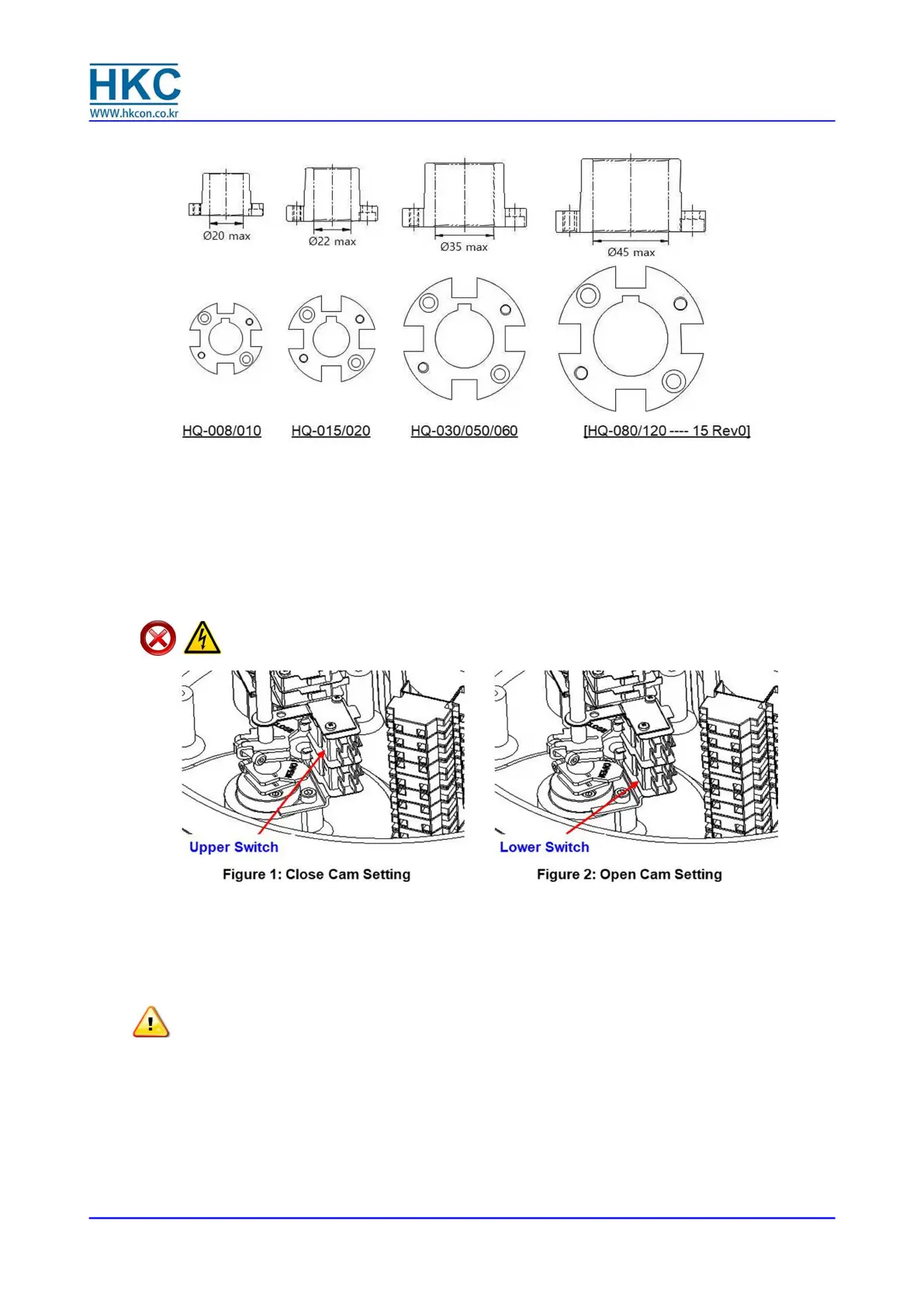
4.3. Limit Switch Setting
4.3.1. Manually rotate the hand wheel of the actuator to fully closed position
4.3.2. Using a hex wrench, loosen the set screw in the CLOSE limit switch cam
4.3.3. Rotate the CLOSE cam towards CW until sounds ‘clicks’ from the limit switch lever. (see Figure 1)
4.3.4. Tighten the set screw with the hex wrench
4.3.5. Manually rotate the hand wheel of the actuator to opened position
4.3.6. Using the hex wrench, loosen the set screw in the OPEN limit switch cam
4.3.7. Rotate the OPEN cam towards CCW until sounds ‘clicks’ from the limit switch lever. (see Figure 2)
4.3.8. Tighten the set screw with the hex wrench
DANGER:
HAZARDOUS VOLTAGE. Make sure all incoming power is disconnected before setting the
limit switch
4.4. Torque Switch Setting
4.4.1. Torque spring, which detects the variation of torque during the operation, is installed to prevent
damaging the valve and actuator under overload condition. Once the actuator is under overload,
the torque switch trips, and the actuator stops immediately.
4.4.2. The torque switches are set by manufacturer on the production site. If re-setting is necessary,
please contact the HKC service representative before setting the torque switch.
CAUTION:
Do not reset torque switch to a setting higher than the maximum setting stated by the
manufacturer.
4.5. Counter-Clockwise to Close Setting
Standard actuators are normally set to clockwise rotation to close. However, the rotation can be reversed
to counter-clockwise to close by simply reconfiguring the wiring as follows:
4.5.1. Reverse wiring in the main terminal block: 9 & 10 as well as 11 & 12.
4.5.2. Adjust the visual indicator to suit the counter-clockwise rotation.
4.5.3. If a PCU card is installed: change P1 (orange) and P3 (grey) on the PCU board.
4.5.4. Move the actuator manually to half-open position and push the auto-reset button once.
4.6. Mechanical Travel Stop Adjustment
 Loading...