HQ Series Quarter-turn Electric Actuator
Installation Operation& Maintenance Manual
Doc No. : HumG-HQ-21 Rev2 Page 12 / 26 Valve Automation Leader, HKC
4.9.3. Standard Specification
Table 1: Standard specification of the Proportional Control Unit
Model PCU EB-V1.5D (for AC) PCU DC-V2.1C (for DC)
Indicated on the board PCU_EB_V1.5D-CONTROL HKC-PCU_DC-MAIN-V2.1C
Special function
Applied Electronic Breaking
(EB) for high resolution control.
NA
Power
110V/220V ac ±10%, 50/60Hz, 4VA max
24V dc ±10%, 7A max
Input signal (set point) 4~20mA dc, 0~20mA dc, 1~5V dc , 0~5V dc , 2~10V dc, 0~10V dc
Input impedance 100 kΩ and over
Output signal (feedback)
4~20mA dc, 0~20mA dc, 1~5V dc , 0~5V dc , 2~10V dc, 0~10V dc
Output impedance 100 Ω and less
Position resistance 100~10 kΩ
Dead time
0.2~7.5 sec (It can be set in 16 step)
•
Step 0 : 0.2 sec
•
Step 1~4 : 0.25~1sec (0.25sec/step)
Step 5~15 : 2.5~7.5sec (0.5sec/step)
Dead band
0.3~7.5 % (It can be set in 16 step)
•
Step 0 ~ 4 : 0.3~0.7 % (0.1 %/step)
•
Step 5 ~ 9 : 1 ~ 1.8 % (0.2 %/step)
Step10 ~15 : 5 ~ 7.5 % (0.5 %/step)
0.4~7.5 % (It can be set in 16 step)
•
Step 0~4 : 0.4~0.8 % (0.1 %/step)
•
Step 5~9 : 1 ~ 1.8 % (0.2 %/step)
Step10~15 : 5 ~ 7.5 % (0.5 %/step)
Fault mode Fail close, Fail open, Fail stop
Position conversion accuracy
±(0.2 to 5)% (may vary depending on conditions)
Ambient temperature -25℃ to 80℃
Ambient humidity 90% RH max. (non-condensing condition)
Dielectric strength 1500V ac, 1 minute 500V ac, 1 minute
Insulation resistance 500V dc, 50MΩ or more
Vibration and shock
X, Y, Z axis 10g (@ 6g RMF), frequency: 0.2-34 Hz, time: within 30 minutes
4.9.4. Main function and usage for PCU
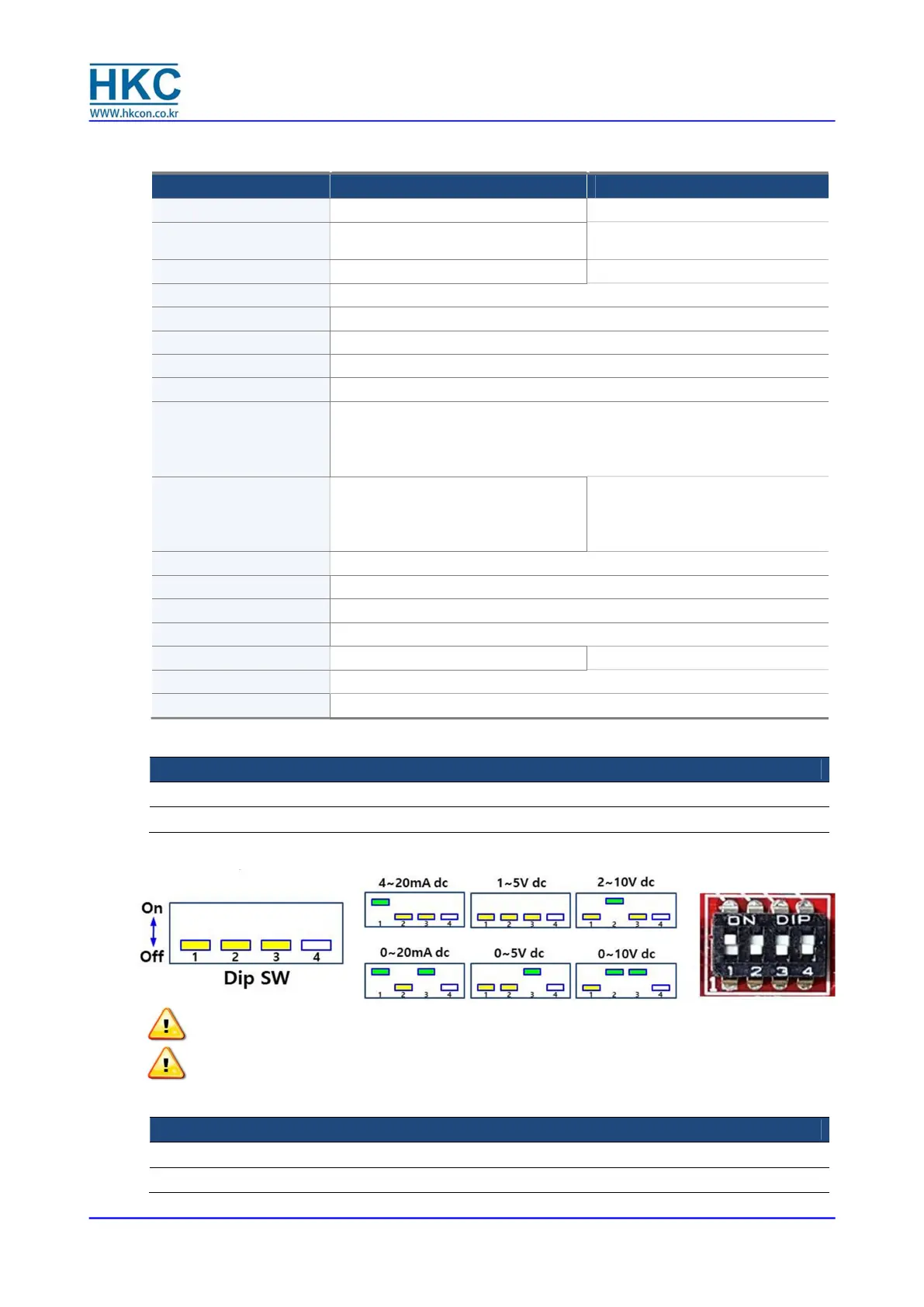
① Select input signal switch
Dip Switch PCU model Power source
SW7 PCU-EB-V1.5D for AC
SW2 PCU-DC-V2.1C for DC
Depending on the system environment, the user can select the required command signal type by
setting the DIP switch SW7 or SW2 as above table.
Notes : DIP switch is commonly set with 4~20mA dc before shipping.
Please make sure whether the input signal and DIP switches are correct as intended use.
Caution : Zero switch (No. 3) is applied to input and output signals equally.
② Select output feedback signal switch
Dip Switch PCU model Power source
SW8 PCU-EB-V1.5D for AC
SW3 PCU-DC-V2.1C for DC
 Loading...