System Hardware: Main Panel
Default Eng. Code - 4567 Default User Code - 1111 (Irl) 1234 (UK)
Ext bell
Int bell
Strobe
Outputs
Aux 12V
Remote Keypad
1
+ +
+
+
B
+
-
-
-
A
--
2
TR
BHO
Z6 Z7
Z1
Z5
Z2 Z3 Z4
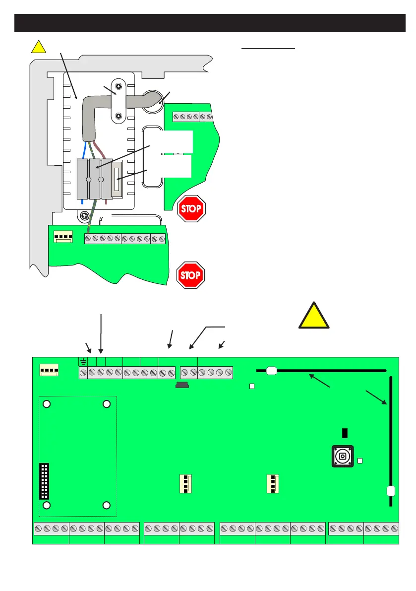
Serial Port 1
Point
ID Bus
Point
ID Bus
Point
ID Bus
Point
ID Bus
Connection
to Power Supply
Connection for
Digi-Modem
}
}
}
}
}
}
}
}
Z8
Z10Z9
Antennas
Tamper Switch
Status LED
Radio
LED
Factory Default
Serial Port 2
JP1
J4 J3
Remote Keypad
(RKP) bus
Auxiliary 12V supply
Zone Inputs (Alarm and Tamper) from 1 to 10
USB
Port
Programmable
Outputs
Bell Hold-Off
Tamper
Return
High-Current
Outputs
Useful Tips
For ease of installation you may
remove lid by pulling out the black
plastic hinges.
Always replace the mains fuse with
the rating indicated.
Always ensure that a good earth is
connected to the unit. This is
required to ensure compliance with
the EMC and LVD directives.
Isolate cables connected to panel
from high voltage cables.
Note: for
best RF
performance
keep wiring away
from antennas
Mains
Entry
Live
Cord
Grip
Neutral
Mains Fuse:
3.15A/250Vac
Anti-surge (T)
Protective
Cover for
Fuse Spur
Isolate mains before commencing any
maintenance on this unit.
After wiring mains, place protective
cover on fuse the spur.
The SW-1070
does not include a disconnect device to
isolate the mains supply. Please ensure
there is such a device fitted externally.
!
!
Note: Red LED for internal purposes only
7
Earth
 Loading...