343-3512A (03/13)
11 of 27
Optimize
1. Replace connector post trim piece with open trim.
2. Remove power pole cover.
3. Insert power pole shell into open trim piece.
4. Install J box to power pole shell.
5. Route power harness through corner connector, power pole, and out of J box.
6. Snap power pole cover into shell.
7. Connect wiring within the J box (by a licensed electrician).
8. Install J box cover.
9. Position ceiling tile trim plates above and below the drop-ceiling tiles and secure with screws and nuts, inserted
from below.
Illustration 1: Optimize Panel Power Pole
Warning
• Connection to the power source should be performed by a licensed electrician in compliance with all national and
local electric codes. Failure to observe this warning could result in a re.
Power Pole Installation
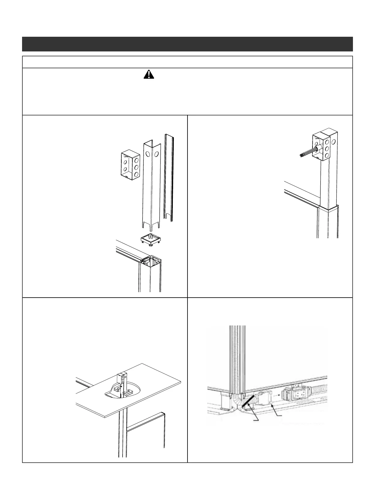
Improperly installed electrical components can fail resulting in personal injury and/or property damage.
Connection to a power source should be performed by a licensed electrician. The previous connection and
the quantity of receptacles used for a given circuit must both be in compliance with all national and local
electrical codes. To prevent personal injury ensure all power sources are disconnected during installation.
WARNING
Use a wire tie to
secure in-feed cable
to panel support.
Connect in-feed cable
to end of power block.
Step 1 - Replace top corner trim
piece with open trim.
Step 2 - Remove power pole
cover.
Step 3 - Insert power pole shell
into open trim piece.
Step 4 - Install J box to power
pole shell.
Step 9 - Position ceiling tile
trim plates above and
below the drop ceiling
tiles and secure with
screws and nuts,
inserted from below.
Step 5 - Route power harness
through corner
connector, power pole,
and out of J box.
Step 6 - Snap power pole cover
into shell.
Step 7 - Connect wiring within
J box (by a licensed
electrician).
Step 8 - Install J box cover
10a. Power pole and J box
Illustration 10. Power Pole Installation
10b. Cable In-feed
10c. Ceiling plate and top caps 10d. Connect to power block
Panel System Installation Packet
343-3890A
(03/17)
Page 10 of 27
 Loading...