IMPORTANT : Customer provides appropriate attachment hardware - wood screws into studs (2-1/2” long minimum)
or molly-type fasteners into drywall. Holes in wall connector are provided for #8 size screws.
NOTE:
• If low point is at the wall, adjust leveling
glides out enough to compensate for
the rise in the oor.
• If high point is at the wall, adjust leveling
glides in enough to compensate for the
drop in the oor.
Step 5 - Ensure panel and wall connector are
plumb against the wall and lightly
mark wall at top and sides of the
wall connector. (If marking wall is not
acceptable use masking tape)
Step 6 - Remove wall connector from panel.
Set panel aside.
Step 7 - With clearance hole of
extrusion at the bottom
and facing away from
wall, position wall
connector against wall
and align top and bottom
of wall connector with
locating makes on wall.
verify plumb with level.
Step 8 - Mark wall connector
hole location onto wall.
Each hole requires
mounting hardware.
Set wall connector
aside.
Step 9 - Drill holes for mounting
hardware if required
Step 10 - Attach wall connector
to wall with appropriate
hardware (2-1/2” long
wood screws into studs,
or molly-type fasteners
into dry wall.
Step 11 - Place the panel onto
the wall connector so the
glide tower tab goes into
the cutout. Secure by
sliding the wall connector
up. (Reference page 3
for attaching panel)
Step 12 - Locate ush against
the wall at the location of
attachment.
Step 13 - Adjust leveling glides as
needed to level panel.
Step 14 - Fit bracket on the panel
and wall connector. Slide
bracket to align with the
holes in the panel.
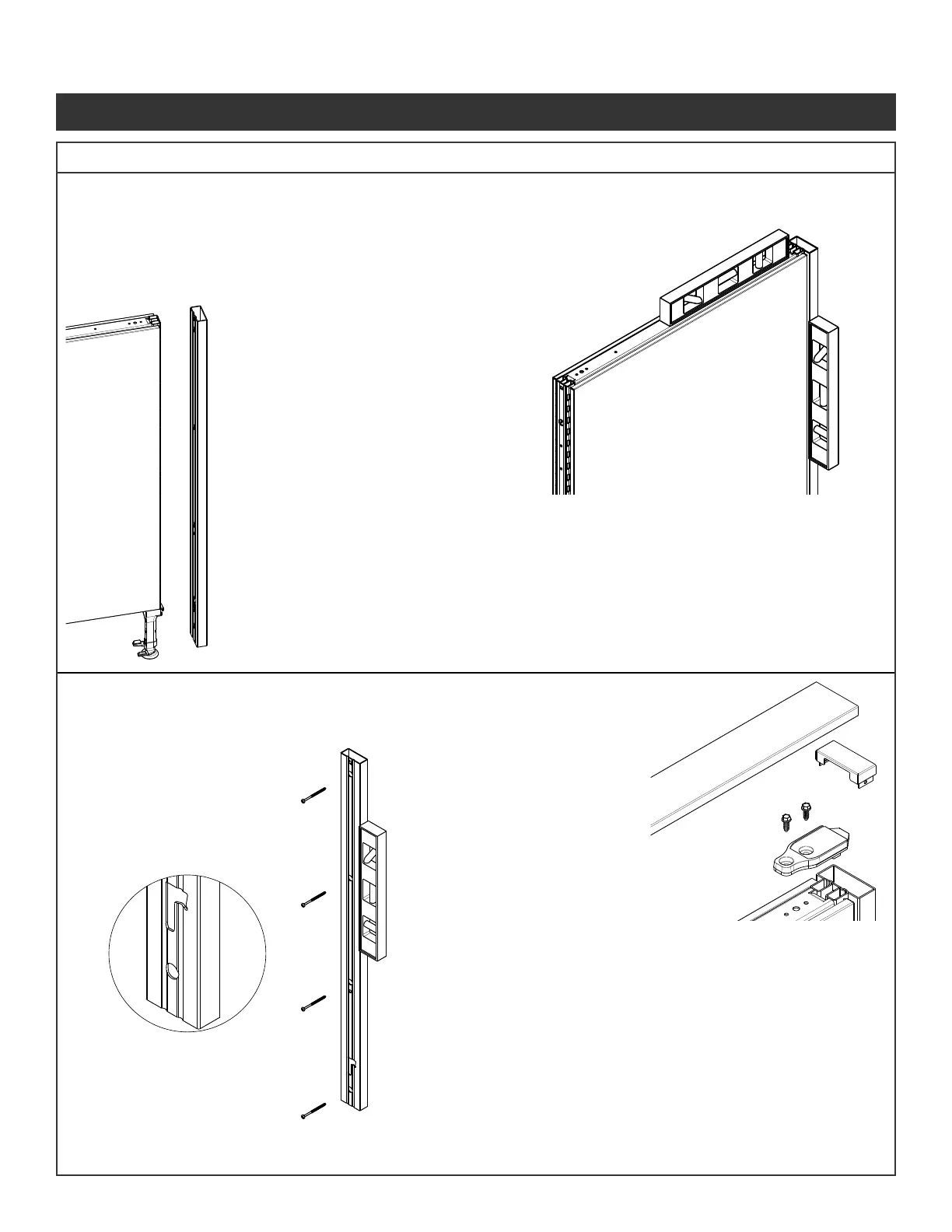
Step 1 - Arrange panel into location required.
Locate cutout in bottom of wall connector
to the glide tower.
Step 2 - Place wall connector
extrusion onto the end of
panel so the glide tower tab
goes into the cutout.
Secure by sliding the wall
connector up.
Step 3 - Locate ush against the
wall at the location of
attachment.
Step 4 - Adjust leveling glides as
needed to level panel.
Step 15 - Attach the brackets to the
panels using the screws
(Fastener #1) provided.
Do not over torque.
Step 16 - Insert wall connector top
cap into wall connector
extrusion.
Step 17 - Panel top cap snaps over
connectors when adjacent
panel is secured into
position
Illustration 8. Panel Wall Connector Installation
Panel System Installation Packet
343-3890A
(03/17)
Page 8 of 27
 Loading...