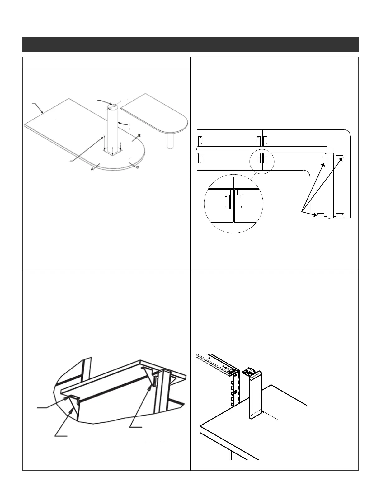
Center line
Support
Column
Leveling
glides
Rear edge
Machine Screws
(into inserts in worksurface)
Right-hand
Support
Bracket
Right-hand
Support
Bracket
Wood
screw
Left-hand
support bracket
Right-hand
support bracket
Note: Countertop Brackets marked ST will not
work on 42” high panels.
Use brackets marked 42 for those panels.
• Install support column so that a center line
through the leveling glides is parallel with the
rear edge of worksurface.
• This applies only to support columns
with two levelers.
Step 2 - Center the countertop across the panel
and install wood screws through holes
in brackets and into countertops.
• Install support column so that it is centered in
the radius end of the pennisula.
Verify the measurements are equal from
3 tangents (marked A, B, C).
Step 1 - Insert the top hook of the bracket into
the top slot of the panel, rotate the
bracket until all of the tabs engage into
the slots.
If one of the following conditions apply:
- A corner countertop positioned at an in-line
variable height junction
- A straight countertop is positioned at an in-line
variable height junction and constrained between
a taller panel and corner countertop
- A straight countertop is positioned at an in-line
variable height junction and constrained between
two taller panels
It is necessary to:
Use ne tooth hacksaw to cut
off 1-5/16” from the bottom of
End Trim vertical cover.
This allows the countertop to t
underneath the End Trim
Illustration 12. Continued
Illustration 12k. Worksurface Support Column
(use with peninsula and D-shaped worksurface)
Illustration 13. Countertop Installation
Illustration 13a. Countertop Bracket Location
Illustration 13b. Countertop Installation
Illustration 13c. Hi-Low Application
Panel System Installation Packet
343-3890A
(03/17)
Page 18 of 27