Trapezoid
Hole
Corner
Connector
Post
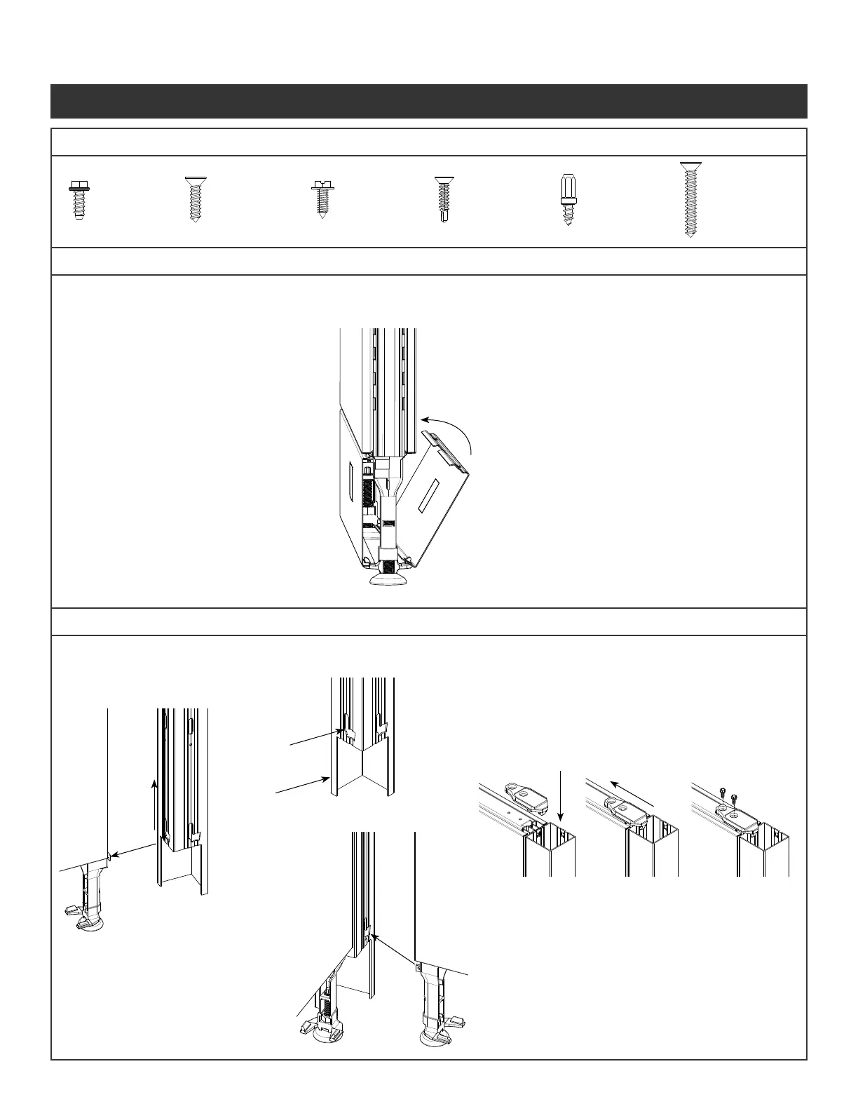
Fastener #1
#10-16x1/2
Hex Head
Fastener #2
#10-16x3/4
Phillips Head
Fastener #3
#8 x 1/2
Hex Head
Fastener #4
#8 x 3/4
Self Drilling
Fastener #5
#10 3/16
Hex Head
Fastener #6
#10 x 1-1/4
Phillips Head
NOTE: If a connection must be lifted
after the screws are installed on a
panel run longer than six feet,
unscrew the panel connector
brackets prior to lifting the panels.
If using stackers, see pg 9.
Step 1 - Arrange panel into location required.
Locate Trapezoid Hole in bottom of
connector to the glide tower.
Step 2 - Secure post by sliding post up until even with vertical.
Step 3 - Fit bracket on the panel and corner connector post.
Slide bracket to align with the holes in the panel.
Step 4 - Attach the brackets to the panels using the screws
(Fastener #1) provided.
Do not over torque
To Remove:
Step 1 -Pull kickplate from top edge by panel
and unhinge from glide towers
To Install:
Step 1 - Place kickplate slots over glide tower tabs.
Step 2 - Press on top of kickplate near glide tower
to snap into place against panel
Step 5 - Lift the second panel up so the glide
tower tab goes into the trapezoid hole.
Step 6 -Ensure panel is fully seated by
checking that the top of post is level
with vertical
Step 7 - Repeat Steps 3 & 4 to secure panel.
Step 8 - Level Panels as they are assembled.
Repeat the other panel connections.
(“T”, “S”, or “X”)
Illustration 2. Panel to Corner Connections
Hardware Included
Illustration 1. Kickplate
Panel System Installation Packet
343-3890A
(03/17)
Page 3 of 27