K
Kristy MartinSep 8, 2025
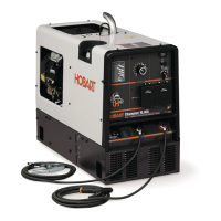
How do I troubleshoot unstable engine speeds on my Hobart Welding Products Welding System?
- Hhenry00Sep 8, 2025
To troubleshoot unstable or sluggish engine speeds on your Hobart Welding Products Welding System, readjust the throttle linkage if necessary and check the throttle solenoid TS1 for smooth operation. Also, tune-up the engine.