BA-21870-001-GB 08.10.2010 5
GB
1. INSTALLATION
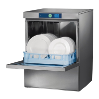
1.1. LOCATION
! Wall clearance is not required at the rear.
! The lateral distance between machine and wall should be at least
400 mm on one side.
! To avoid damage of the feet, do not slide the machine on floor after
the skid is removed.
! Level machine by turning the feet.
! Distribute machine weight equally onto all feet.
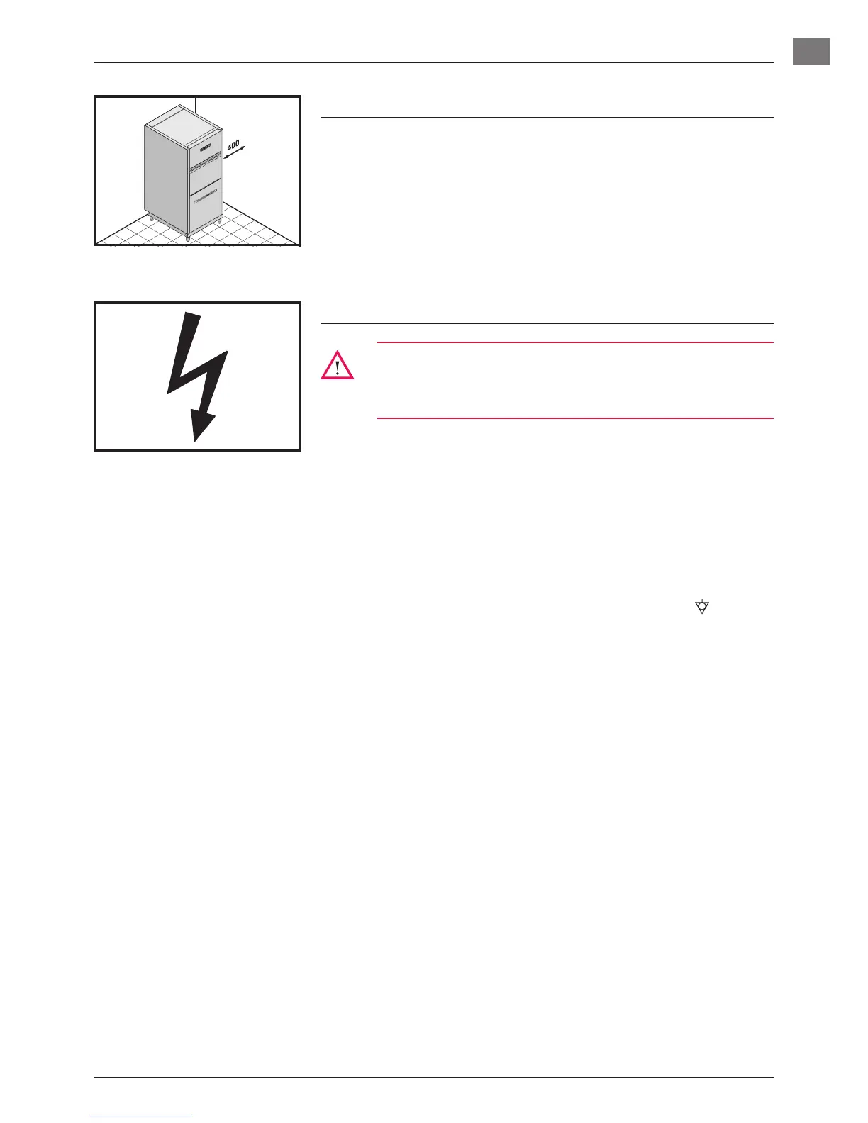
1.2. ELECTRICAL CONNECTION
Must be carried out by an authorized technician according to
the local and national codes.
For Australia: in accordance with AS/NZS3500.1
! The electrical supply shall comply with the name-plate data.
! Modification to a different electrical supply is possible within the
range of variations designated in the circuit diagram.
! Line fuses and cable cross section shall comply with the require-
ments.
! A cut-off device shall be provided to connect the supply cord (isolat-
ing switch or accessible plug device).
NOTE: According to EN 60 335 the appliance must be connected to
an equipotential conductor. The connecting screw (
) is locat-
ed at the rear of the floor pan beside the cable inlet.
 Loading...