BA / ETL duolift MTE 3000 – 94 12 554
10
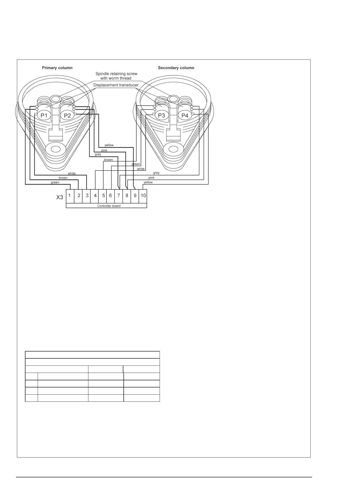
Fig. 5 Displacement transducers
The displacement transducers operate as voltage
dividers.
Transducers P1 and P3 control the synchronism
and give the signal for emergency stop. They
must have the same voltage relative to each o-
ther.
P2 and P4 supply only the signal for the second
emergency stop and must also have the same
voltage relative to each other.
The voltage values are a function of carriage po-
sition.
The basic voltage values are adjusted at a carri-
age height of 450 mm (measured from the co-
lumn base plate to the upper edge of the swing
arm support on the lifting carriage).
The voltages can be measured on the displace-
ment transducers or on terminal strip X3.
BASIC VALUES
Measuring points
Transducer Terminals Volt
P1
green < > white 1 < > 3 2.10
P2
pink < > yellow 8 < > 9 9.10
P3
green < > white 4 < > 6 2.10
P4
pink < > yellow 8 < > 10 9.10
In order to adjust these values, press the relative
displacement transducer against spring force
from the worm until the cogwheel is free to rotate
and the proper setting is reached.
Afterwards lower the lift and turn P3 absolutly to
the right side. Then drive back leftside only 2
tteeth. Turn P1 to the right side until both light
diodes are on. Raise and lower the lift one time to
ist upper and lower position. Any differences bet-
ween swing arms can be adjust by P1. Turning
the gear of P1 one tooth to the right side lowers
the carriage of the slave column about 5mm. If
you turn the gear of P1 one tooth to the left side.
The carriage of the slave column will will raise
about 5mm. To adjust the second security switch
raise the lift about 800 mm. Adjust P1-3 to 0 ±
0,005 Volt. To adjust exactly, loose the screw of
the axle of P1 to 0 ± 0,005 Volt. When tightening
the screw again, be sure not to displace P1.
Turn P2 right side until both light diodes are out.
Mark the working tooth of P2. Afterwards turn P2
to the left side until both LED are on and out a-
gain. Mark the working tooth again. Now choose
the tooth between both markings and put it onto
the thread. The adjustment is completed.
The adjustment of the upper and lower limit
switch is controlled by a steel cabel which is con-
nected by a plate with the main switch . The lower
und upper limits can be changed by adjusting the
the position of the steel plate sitting at the bottom
of the post.
 Loading...