Do you have a question about the Hofmann geodyna 6800 and is the answer not in the manual?
Provides guidance on reading the manual and explains used symbols for better understanding of text and images.
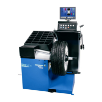
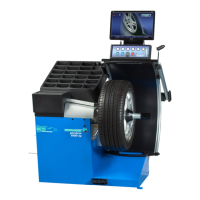
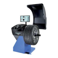
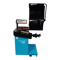
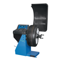
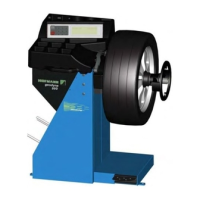
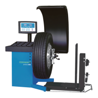
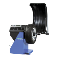
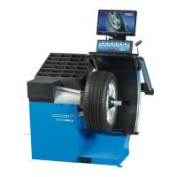
Describes the machine's purpose for dynamic/static balancing of car and light-truck wheels up to 70 kg and 950 mm diameter.
Outlines general safety rules for operation, modifications, electrical work, and personal protective equipment.
Explains the function of the screen, keys, geodata arms, balancing modes, and main shaft lock.
Describes the keypad layout and the function of individual keys like Menu, ESC, HELP, START, STOP, loudspeaker, and indicator light.
Explains the screen layout, including information fields, menu fields, and the main display area for data.
Illustrates and defines pictograms used for wheel types, balancing modes, and geodata arm functions.
Explains the assignment and function of menu keys (F1-F6) and the different types of menu fields.
Guides on powering on the machine, its self-tests, and the initial display of the main menu.
Lists and explains error messages that may occur during machine startup, including system communication and calibration errors.
Instructions for mounting the wheel clamping device onto the main shaft, emphasizing cleanliness.
Explains how to perform a compensation run to compensate for residual unbalance in clamping means.
Instructions for clamping car and light-truck wheels, including notes on rim dimensions and contact surfaces.
Guides on selecting the wheel type from the FELGENTYP screen using menu keys.
Explains how to enter weight placement for different balancing modes (normal, Alu 1-5) using menu keys.
Guides on entering rim dimensions (width, diameter, distance) for standard balancing, recommending automatic measurement.
Illustrates correct gauge head contact positions on different rim types for accurate measurements.
Instructions for applying adhesive weights for Alu 1-5 balancing modes using the geodata gauge arm and marking positions.
Instructions for manually entering the distance if automatic measurement fails, referencing relevant figures.
Instructions for manually entering the rim diameter if automatic measurement fails, referencing relevant figures.
Instructions for entering rim dimensions for special cases (type 3) when programmable modes are not applicable.
Instructions for entering rim dimensions for static unbalance display, especially for narrow wheels.
Explains how to save wheel profiles, including stored data like dimensions, weight positions, and type.
Explains how to access the BALANCING screen and start a measuring run, and post-measurement actions.
Details the precise fitting of spring weights and adhesive weights for all balancing modes.
Instructions for fitting adhesive weights with the gauge head, covering error codes and system behavior.
Guides on fitting adhesive weights manually when gauge head access is limited, emphasizing accurate positioning.
Details performing a check run, interpreting the OK status, and handling residual unbalances.
Explains static unbalance correction, its display, and when it is applied instead of dynamic balancing.
Provides recommendations for fitting weights for static unbalance correction based on wheel type and unbalance levels.
Explains that behind-the-spokes placement is auto-activated in Alu 2 and Alu 3 modes and can be selected.
Guides on selecting balancing mode, behind-the-spokes placement, and inputting wheel data, including spoke count selection.
Guides on closing the wheel guard, performing the measuring run, and fitting adhesive weights in left and hidden positions.
Explains that factory settings are usually sufficient, but modes can be changed via code entry for special cases.
How to access the FUNCTIONS menu from the main menu.
Guides on selecting a mode of operation using menu keys and wheel rotation.
Instructions on how to change values for selected modes of operation using menu keys and wheel rotation.
Explains the machine's counters for measuring runs, optimizations, and service intervals.
Guides on entering promotional text using the TEXT EDITOR screen, character set, and text field.
Error E1: Incorrect or incomplete rim dimension input, requires re-entry.
Error E2: Wheel guard is not closed, requires closing.
Error E3: Geodata gauge arm for distance/diameter is not in home position.
Error E4: Geodata width gauge arm is not in home position.
Error E5: Compensation range exceeded due to clamping device unbalance.
Error E6: Calibration weight was not fitted during readjustment.
Error E7: Cannot choose weight placement for the current wheel type.
Error E8: Valve position not entered, specific to optimisation/minimisation programs.
Error E88: Main shaft rotating speed exceeds safety limit.
Error E89: Jammed key or engaged pedal switch, requiring troubleshooting or service.
Error E92: Geodata gauge arm for distance/diameter is defective, requiring service or manual input.
Error E93: Geodata width gauge arm is defective, requiring service or manual input.
Explains fatal error codes (alphanumeric) appearing during internal monitoring or self-test, and when to contact customer service.
Explains optimisation as matching rim and tyre for better running conditions and reduced weight, or weight minimisation.
Guides on interrupting, continuing, or restarting optimisation/minimisation programs, and how the machine handles interruptions.
Guides on starting optimisation or weight minimisation, including tyre mounting, clamping, and dimension entry.
Instructions to start the weight minimisation process via the MINIMIEREN 1 screen.
Instructions to start the run-out optimisation process via the OPTIMIEREN 1 screen.
Guides on continuing weight minimisation and run-out optimisation, including wheel rotation and marking.
Explains when and how the operator can readjust the machine due to measurement inaccuracies.
Important note that readjustment requires the factory-supplied clamping adaptor.
Step-by-step guide for performing the readjustment procedure, including machine preparation and calibration runs.
General maintenance advice, emphasizing power disconnection and cleanliness of clamping components.
Step-by-step instructions for replacing the halogen lamp for inner rim lighting, including safety notes.
Contact information for customer service in Germany for troubleshooting unresolvable issues.
Lists technical specifications of the machine, including dimensions, weight, power, and working range.
Declaration of conformity for the tyre changer with EC directives and harmonized standards.
| Type | Automatic Wheel Balancer |
|---|---|
| Rim Width | 1.5 - 20 inches |
| Display | LCD |
| Max Wheel Width | 20 inches |
| Balancing Accuracy | 1 g |
| Power Supply | 230V 50/60 Hz |
| Wheel Diameter Range | 10 - 30 inches |
| Rim Diameter | 10 - 30 inches |