Do you have a question about the Hofmann geodyna 6900-2p and is the answer not in the manual?
Explains special features used in the manual for easier reading and understanding of illustrations and instructions.
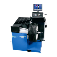
Defines the static and/or dynamic balancing of car, SUV, and light-truck wheels up to 70 kg and 950 mm diameter.
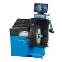
Details the color screen display, menu functions, and keypad layout for machine operation.
Explains acquiring wheel parameters using laser scanner and sonar sensor or manual keypad entry.
Describes display options for weight position on the rim depending on wheel type.
Explains automatic measurement process, stopping, and display of unbalance amounts and locations.
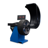
Describes the mandatory wheel guard with electric interlocking and its function.
Explains the pedal-operated main shaft lock for wheel positioning and its dual function.
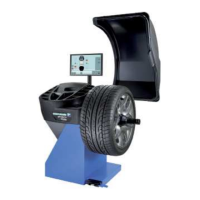
Describes the integrated measuring caliper for rim distance and diameter measurement.
Provides instructions for unpacking the machine, advising to cut packing strips and unscrew fasteners.
Explains how to tilt and move the machine for transportation on site, using lifting equipment.
Lists the unit's documentation: Safety Booklet, Operator's Manual, Service Manual.
States that installation instructions are provided in Chapter 2.
Describes the machine's keypad, including menu keys, ESC, HELP, START, STOP, and cursor controls.
Details the screen layout, including status bar, display field, and menu fields.
Illustrates pictograms used on the screen for wheel types, rim types, and balancing modes.
Explains various balancing modes (Alu 0-5) and gauge arm functions.
Explains menu fields on the screen, their assignment, and how to select functions via pull-down menus.
Explains how to display help information for current actions and error codes.
Describes the pedal-operated main shaft lock for wheel positioning and POWER CLAMP control.
Explains the laser scanner and sonar sensor for wheel dimension acquisition.
Explains the Geodata arm's function for rim measurement and adhesive weight application.
Details factory-adjusted operating modes available immediately after power-on, including PROFILING and Weight mode 1.
Lists error codes (E) for operational errors, warnings (H), and fatal errors (300/C10).
Details fitting the Power Clamp device, including moving jaws and screwing components.
Details clamping the wheel, including jaw movement, centring cone, and sleeve application.
Explains preparing the clamping device without a wheel for calibration.
Describes performing a compensation run to compensate for residual unbalance in clamping means.
Explains the use of the gauge for acquiring wheel data only in MANUAL mode.
Explains correct gauge head application on various rims and weight fitting positions for accurate measurement.
Lists basic information needed for imbalance calculation: vehicle type, balancing mode, rim width/diameter, and distance.
Explains how Easy Alu function automatically recognizes Alu and rim parameters.
Explains manual rim dimension reading and setting, emphasizing accurate entry for optimization.
Details manual ALU selection based on gauge contact points and desired weight location.
Guides user on accessing the BALANCING or RIM DATA ENTRY screen for settings.
Explains using special dimensions mode for complex wheel parameters outside automated functions.
Details memorizing wheel types for frequent balancing to save data entry time.
Explains how to reset rim dimensions and measurement methods by returning to RIM DATA ENTRY screen.
Describes checking the wheel for radial and lateral run-out before the measuring run.
Describes specific functions of the balancer in PROFILING mode.
Explains changing weight position using Laser Pointer and geodata arm.
Describes saving data from the first rim of a group to reduce data acquisition time for subsequent wheels.
Details the measuring run process, including unbalance display and weight application points.
Allows for precise detection of rim spokes for accurate behind-the-spokes weight placement.
Lists preliminary steps: compensation run, wheel clamping, vehicle type selection, and rim dimension reading.
Details launching a measuring run and interpreting the balancing screen results.
Explains static unbalance measurement and correction for small wheels.
Details fitting balancing weights for different modes, including clip-on and adhesive weights.
Details fitting balance clips on the left and right correction planes, including cleaning and positioning.
Explains fitting adhesive weights using the gauge head, emphasizing correct positioning and cleaning.
Explains fitting adhesive weights based on entered dimensions when gauge arm is inaccessible.
Explains using the laser pointer for precise indication of adhesive weight positions.
Details performing a test run after applying balance weights to verify correct balancing.
Details activating behind-the-spokes placement via F5 menu after entering spoke count.
Explains fitting adhesive weights on the left side of the rim disc and applying hidden weights.
Defines optimisation as finer matching and weight minimisation as matching without optimisation.
Details starting and suspending optimisation or minimisation cycles using F4 and F3 keys.
Explains how to start the weight optimisation and minimisation procedures.
Details how to restart an interrupted optimisation/minimisation cycle using the F3 key.
Details the steps for the minimisation cycle, including valve position entry and start.
Details the steps for the optimisation cycle, including valve position entry and start.
Explains how to finish weight minimisation or optimisation and interpret resulting codes.
Explains how to permanently save changes to operating modes in memory.
Details saving modes to permanent memory, acknowledging acceptance with a signal.
Lists available operating modes and their recommended settings.
Refers to Chapter 5 for machine power-on and recommended mode settings.
Explains how to select menu language from available options.
Describes adjusting audible signal volume and saving the selection.
Explains how measuring runs are stored and lists available counter types.
Details entering promotional text using the TEXT COMPOSITION mode and menu key functions.
Describes the text field layout and character entry using menu keys and scroll command.
Explains how to save, undo, or delete entered text using F5 key options.
Lists error codes (E) for operational errors.
Lists error codes (H) for warnings.
Lists error codes (300 or C10) for fatal errors.
Explains how error messages are indicated by acoustic signals.
Details user calibration steps, including ensuring the clamping tool is on the shaft and pressing F6.
Details replacing the internal wheel light, including removing the panel and unplugging the lamp.
Details technical data including distance, width, diameter, and weight of wheels.
Details unbalance weight resolution and suppression settings by vehicle type.
Specifies rim dimensions (distance, width, diameter) by vehicle type and unit.
| Brand | Hofmann |
|---|---|
| Model | geodyna 6900-2p |
| Category | Wheel Balancers |
| Language | English |