Do you have a question about the Hofmann geodyna 4500-2p and is the answer not in the manual?
Main operational instructions for the wheel balancer.
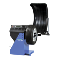
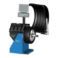
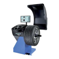
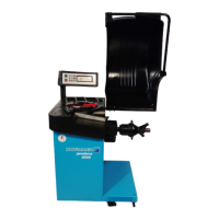
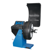
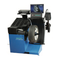
Identifies the machine as a car wheel balancer.
Manual for the machine operator.
Defines the intended use and scope of application for the wheel balancer.
Details the intended use and limitations of the wheel balancer.
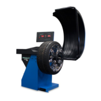
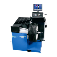
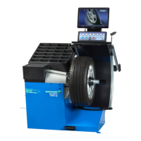
Visual overview of the wheel balancer components.
Diagram showing the front and rear views of the wheel balancer.
Description of the keyboard and display elements.
Functionality of the gauge arm for measurements.
Explanation of weight placement selection.
How measurement runs and values are displayed.
Description of the pedal brake for the main shaft.
Details the control panel layout and display information.
Functionality of the measurement arm for rim data input.
Explanation of different balancing modes available.
Process and output of the automatic measurement cycle.
Function of the pedal-operated lock for the main shaft.
Procedure for unpacking the machine from its packaging.
Steps for safely unpacking the machine.
How the wheel guard affects machine functions.
Explains the impact of the wheel guard on machine modes.
Procedure for attaching the weight tray holder.
Overview diagram of controls and displays.
Diagram of the keypad with function keys.
General view of the control panel and its elements.
Detailed layout of the function keys.
Error codes that may appear at power-on.
List and explanation of errors occurring during startup.
Error code for low line voltage.
Error code for high line voltage.
Error code for overvoltage.
Error for low line voltage (under 170V).
Error for high line voltage (over 265V).
Error for overvoltage (over 275V).
Steps to mount the wheel clamping and centering device.
How to install the wheel adaptor onto the main shaft.
Details on the MZV-4 center bore adaptor.
Information on USV and SCA universal adaptors.
Diagrams showing wheel adaptor fitting.
Details of the MZV-4 adaptor for center bore rims.
Information on universal adaptors for various rim types.
Diagram of center bore clamping device.
Diagram of universal clamping device.
Steps to mount the motorcycle wheel adaptor.
Diagram of motorcycle wheel adaptor.
Diagram of cone adaptor for center bore wheels.
Diagram of universal adaptor for stud hole or closed rims.
Steps to fit the motorcycle wheel adaptor.
Diagram of the motorcycle wheel adaptor.
Procedure for clamping motorcycle wheels.
Balancing procedure in manual mode.
Balancing procedure in automatic mode.
Balancing using the Easy Alu feature.
Instructions for manual balancing operation.
Instructions for automatic balancing operation.
Utilizing the Easy Alu function for balancing.
Starting a measurement run using START or wheel guard.
Example of display and correction for the right correction plane.
How to initiate the measurement run.
Example of right plane display and correction.
How to fit balance clips.
How to fit adhesive weights using the gauge head.
Instructions for fitting clip-on weights.
Method for applying adhesive weights with the gauge head.
Determining hidden weight positions for Alu 2P.
How to enter the vehicle type.
How to input weight placement data.
How to input the vehicle type.
How to select and input balancing modes.
Determining and entering rim width.
Inputting measurement for static unbalance display.
Setting value for static unbalance display.
Automatic determination of distance and diameter.
Automatic determination of rim measurements.
Auto-determination of distance and diameter.
Automatic determination of rim width.
Checking run-out without the wheel guard.
Checking run-out with the wheel guard.
Procedure for checking run-out without the wheel guard.
Procedure for checking run-out with the wheel guard.
Selecting balancing mode and inputting wheel data for this technique.
Selecting balancing mode and entering wheel data.
How to fit a hidden adhesive weight.
Diagram showing display and correction of the right correction plane.
Method for fitting hidden adhesive weights.
Critical error messages.
Critical error messages.
Critical error for low line voltage.
Critical error for high line voltage.
Critical error for overvoltage.
Critical error for low line voltage.
Critical error for high line voltage.
Critical error for overvoltage.
Instructions for operating optimisation/minimisation programs.
Instructions for operating optimisation and weight minimisation programs.
How to perform run-out optimisation.
How to perform weight minimisation.
Procedure for optimising wheel run-out.
Procedure for weight minimisation.
Display Un.5 - reference mark.
Procedure for readjustment using code C14.
Close guard, press START for first readjustment run.
Screw calibration weight into adaptor base.
Press START for second readjustment run.
Procedure for readjustment using code C14.
Close guard, press START for first readjustment run.
Screw calibration weight into adaptor base.
Press START for second readjustment run.
Information on contacting customer service.
Information on contacting customer service.
Technical specifications of the machine.
| Measuring speed | 200 rpm |
|---|---|
| Balancing Speed | 200 rpm |
| Rim width | 1.5 - 20 inches |
| Rim diameter | 10 - 30 inches |
| Wheel width | 1 - 20" |
| Wheel Diameter Range | 10 - 30 inches |
| Max Wheel Weight | 154 lbs |
| Power Supply | 50/60 Hz |