Do you have a question about the Hofmann geodyna 7600 and is the answer not in the manual?
Describes maintenance, checks, and repairs for the wheel balancer, intended for qualified personnel.
Lists standard and special tools necessary for repairing and checking the wheel balancers.
Provides essential safety precautions to follow when using the wheel balancer equipment.
Outlines crucial safety measures related to electrical connections and handling within the unit.
Details the procedure for safely isolating equipment from its power source during maintenance.
Specifies the electrical requirements and notes for installation and power source verification.
Explains the AC power distribution and drive motor operation within the balancer.
Describes the DC power distribution and operation of various components like IBP board and encoders.
Explains how the wheel balancer computes static and dynamic imbalance using various sensors.
Provides guidelines for ensuring the balancer is placed on a well-leveled floor for accurate operation.
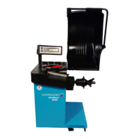
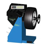
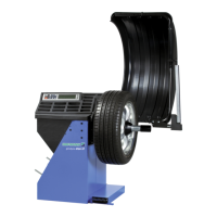
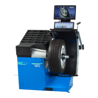
Lists the main components of the balancer, including IBP Box, Vibratory Assembly, and Sonar.
Details the IBP box as a multifunctional device integrating controller and power supply.
Describes the PEM unit, which includes switch, fuses, and power supply inlet.
Explains the IBP board as the integrated controller and power supply, with software loading via MMC/SD card.
Details the two capacitors (10 and 20 uF) used for starting the motor.
Describes the Virtual Plane Measurement vibratory assembly technology and its components.
Explains the function and installation of transducers for measuring unbalance forces.
Details the temperature sensor's role in compensating for temperature-dependent force conversion.
Explains how incremental encoders capture rotational travel, direction, and absolute angular position.
Describes the encoder board located in the vibratory tube, used for tracking shaft rotation.
Details the encoder board for the power clamp, sensing pulley rotation for tie-rod movement.
Explains the motor's function in accelerating, maintaining, and stopping the shaft for measurements.
Highlights the importance of proper belt tension for drive system friction and measurement accuracy.
Describes the different brake designs used for decelerating the main shaft after measurement.
Explains the economical brake system that uses motor torque reversal for deceleration.
Details the mechanical brake operated by pedal to lock the motor pulley.
Explains the electromagnetic brake's function in stopping the wheel assembly at TDC.
Describes the components and function of the power clamping device for securing the wheel.
Explains the SAPE arm for measuring rim reference points and entering stick-on weights.
Describes the sonar sensor's use in reading rim width and detecting distance.
Details the sonar sensor's role in detecting rim information for width measurement.
Introduces the chapter's focus on checking and replacing balancer components.
Provides steps for checking and replacing the power supply cable.
Details how to access the internal components of the balancer.
Explains the procedure for accessing and removing the IBP box.
Guides on checking and replacing the power entry module and its fuses.
Provides troubleshooting steps and replacement procedures for the IBP board.
Details the checking and replacement process for transducers on the alloy VPM.
Explains how to check and replace the balancer's drive motor.
Guides on checking and replacing the power clamp nut and tie rod assembly.
Provides steps for checking and replacing the electromagnetic brake.
Details the procedure for checking and replacing the distance potentiometer.
Explains how to check and replace the diameter potentiometer.
Guides on checking and replacing the laser pointer assembly.
Details the procedure for checking and replacing the wheel guard hood switch.
Explains how to check and replace the sonar sensor.
Provides steps for checking and replacing the touch screen.
Introduces error codes, beep codes, and service codes for diagnosing malfunctions.
Details the step-by-step process for updating the balancer's software using an SD card.
Describes the sequence of service codes to perform after software download.
Lists common service codes recommended for checking system components and diagnosing errors.
Explains the self-test procedure performed upon machine startup and error code indications.
Lists and explains 'H' error codes, which are hints that do not lock the machine.
Details error codes related to the IBP box and their potential causes and solutions.
Explains 'K' codes, which are kernel codes representing software-detected errors.
Describes EEP codes, which are beep sequences used to recognize machine malfunctions.
Explains the purpose of service codes: calibration, settings, diagnostics, and software upgrades.
Provides a comprehensive list of service codes available for the balancer.
Details how to access and navigate the service menu using C codes.
Explains how to save operational settings and calibration data using code C90.
References user-configurable C codes for settings like unbalance display, wheel dimensions, and calibration.
| Brand | Hofmann |
|---|---|
| Model | geodyna 7600 |
| Category | Wheel Balancers |
| Language | English |