HOMELITE ALL-TEMP Multi-Purpose GREASE
This
special
grease
which works
under low temperature as well as
high-temperature conditions is
available in half-pound
(8
ounce)
cans as
Part
No.
24551.
Use
it lor
the following applications:
2.
After
cleaning
starter rewind spring, apply a very
small amount to each
side of the coiled
spring with
your
fingers.
3, Whenever
starter is removed, clean
pulley
shaft
and
apply a
small amount
lo
pulley
shaft
with
your
fingers.
(This
lubricates the
rotor nut
bearing.)
4. Whenever clutch is
removed for
service, wipe a small
amount
onto the clutch
needle
bearings with
your
fingers.
Daify, in needle nose Lube
Gun
#24258
to lubricate
nose
bearing ol sprocket
nose
bars through lube hole
ALL{EMP
,llutti-furpo*
cr{EAs€
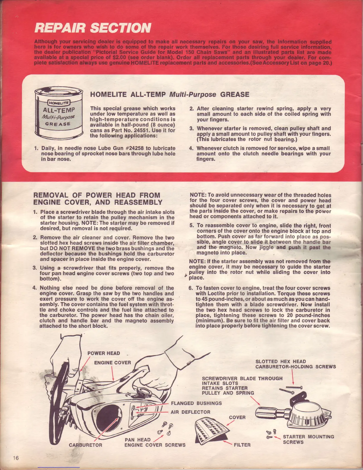
REMOVAL
OF
POWER
HEAD FROM
ENGINE
COVER,
AND
REASSEMBLY
1.
Place
a screwdriver blade through the
air
intake
slots
of
the starter to retain the
pulley
mechanism in
the
starter housing. NOTE: The starter may
be
removed if
desired,
bul
removal
is not required.
2. Remove the
air cleaner and cover. Remove the
two
slotted hex head screws inside the
air filter chamber,
but DO
NOT REMOVE the two brass bushings and the
deflector because lhe
bushings hold the carburetor
and spacer in
place
inside the
engine
cover.
3. Using a screwdriver that fits
properly,
remove
the
four
pan
head
cngine
cover screws
(two
top and two
bottom).
4, Nothing else need be
done
belore removal
of
the
engine cover. Grasp the
saw
by the two
handles and
exert
pressure
to work the
cover oll
the
engine
as-
sembly.
The
cover contains the fuel
system
with
throt-
tle and choke controls and the fuel line attached
to
the
carburetor. The
power
head has the
chain oiler,
clutch
and
handle
bar
and
the
magneto assembly
attached to the
short
block.
POWER HEAD
ENGINE COVER
NOTE: To
avoid
unnecessary
wear of the threaded
holes
for the four
cover screws, the
cover and
power
head
should be separated
only when it is necessary
to
get
at
the
parts
inside the cover,
or
make
tepairs
to the
power
head or components
attached to it.
5. To reassemble
cover to
engine, slide the
right, front
corners of the cover
onto the engine
block
at top and
bottom. Push cover as
far lorward
into
place
as
pos-
sible,
angle
cover to
slide
it between
the handb
brr
and
the magneto. Now
jiggle
and
puCr
lt
p-
b
magneto
into
place.
NOTE:
ll the starter assembly was not removed from
the
engine
cover,
it may be necessaty
to
guide
the starter
.
pulley
into the rolor nut
while sliding the cover into
t
place.
6.
To fasten cover lo engine, treat the four cover screws
with Loctite
prior
to installation.
Torque these
screws
to 45
pound-inches,
or about as much as
you
can hand-
lighten them with a blade screwdriver. Now install
the two hex head screws to lock the carburetor in
place,
tightening these screws to 20
pound-inches
(minimum).
Be sure to
lit
the air
filter
and cover back
into
place properly
before tightening lhe cover screw.
I
I
t
SLOTTED HEX HEAD
SCREWDRIVER
BLADE
THROUGH
INTAKE SLOTS
RETAINS STARTER q
PULLEY AND SPRING
FLANGED
BUSHINGS
AIR DEFLECTOR
ENGINE COVER SCREWS
w::

 Loading...