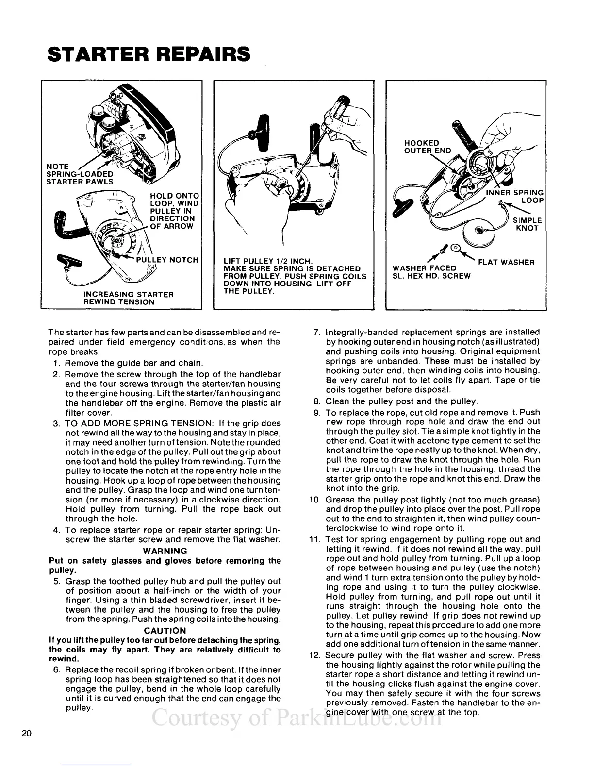
STARTER REPAIRS
HOLD ONTO
LIFT PULLEY
112
INCH.
MAKE SURE SPRING IS DETACHED
FROM PULLEY. PUSH SPRING COILS
DOWN INTO HOUSING.
LIFT OFF
THE PULLEY.
FLAT WASHER
WASHER FACED
SL. HEX HD. SCREW
The starter has few parts and can be disassembled and re-
paired under field emergency
conditions,as when the
rope breaks.
1. Remove the guide bar and chain.
2. Remove the screw through the top of the handlebar
and the four screws through the
starter/fan housing
to the engine housing. Lift
thestarter/fan housing and
the handlebar off the engine. Remove the plastic air
filter cover.
3.
TO
ADD
MORE SPRING TENSION:
If the grip does
not rewind all the way to the housing and stay in place,
it may need another turn of tension. Note the rounded
notch in the edge of the pulley. Pull out
thegrip about
one foot and hold the pulley from rewinding. Turn the
pulley to locate the notch at the rope entry hole in the
housing. Hook up a loop of rope between the housing
and the pulley. Grasp the loop and wind one turn ten-
sion (or more if necessary) in a clockwise direction.
Hold pulley from turning. Pull the rope back out
through the hole.
4.
To replace starter rope or repair starter spring: Un-
screw the starter screw and remove the flat washer.
WARNING
Put on safety glasses and gloves before removing the
pulley.
5.
Grasp the toothed pulley hub and pull the pulley out
of position about a half-inch or the width of your
finger. Using a thin bladed screwdriver, insert it be-
tween the pulley and the housing to free the pulley
from the spring. Push the spring coils
intothe housing.
CAUTION
If you lift the pulley too far out before detaching the spring,
the coils may fly apart. They are relatively difficult to
rewind.
6.
Replace the recoil spring if broken or bent. If the inner
spring loop has been straightened so that it does not
engage the pulley, bend in the whole loop carefully
until it is curved enough that the end can engage the
pulley.
7.
Integrally-banded replacement springs are installed
by hooking outer end in housing notch (as illustrated)
and pushing coils into housing. Original equipment
springs are unbanded. These must be installed by
hooking outer end, then winding coils into housing.
Be very careful not to let coils fly apart. Tape or tie
coils together before disposal.
8.
Clean the pulley post and the pulley.
9.
To replace the rope, cut old rope and remove it. Push
new rope through rope hole and draw the end out
through the pulley slot. Tie asimple knottightly in the
other end. Coat it with acetone type cement to set the
knot and trim the rope neatly up to the knot. When dry,
pull the rope to draw the knot through the hole. Run
the rope through the hole in the housing, thread the
starter grip onto the rope and knot this end. Draw the
knot into the grip.
10. Grease the pulley post lightly (not too much grease)
and drop the pulley into place over the post. Pull rope
out to the end to straighten it, then wind pulley coun-
terclockwise to wind rope onto it.
11.
Test for spring engagement by pulling rope out and
letting it rewind. If it does not rewind all the way, pull
rope out and hold pulley from turning. Pull up a loop
of rope between housing and pulley (use the notch)
and wind 1 turn extra tension onto the pulley by hold-
ing rope and using it to turn the pulley clockwise.
Hold pulley from turning, and pull rope out until it
runs straight through the housing hole onto the
pulley. Let pulley rewind. If grip does not rewind up
to the housing, repeat this procedure to add one more
turn at a time until grip comes up to the housing. Now
add one additional turn of tension in the same manner.
12. Secure pulley with the flat washer and screw. Press
the housing lightly against the rotor while pulling the
starter rope a short distance and letting it rewind un-
til the housing clicks flush against the engine cover.
You may then safely secure it with the four screws
previously removed. Fasten the handlebar to the en-
gine cover with one screw at the top.
 Loading...