EasyManua.ls Logo

Homestyles 5542 49 User Manual

Homestyles 5542 49
10 pages
To Next Page IconTo Next Page
Page #1 background imageLoading...
Page #1 background image
Hardware List
5542 49-
Hall Tree
E.
Middle Panel
1 pc.
U.
Door
1 pc.
A.
Top
1 pc.
B.
Shelf
1 pc.
G.
Seat
1 pc.
J.
Front Rail
1 pc.
O.
Back Rail
1 pc.
P.
Back Panel
1 pc.
T.
Side Panel
1 pc.
D.
Side Panel
1 pc.
F.
Foot
4 pcs.
K.
Back Rail
2 pcs.
L.
Back Rail
1 pc.
N.
Back Rail
1 pc.
M.
Back Panel
1 pc.
Q.
Back Panel
2 pcs.
C.
Side Panel
1 pc.
S.
Side Panel
1 pc.
R.
Back Upright
1 pc.
V.
Door
1 pc.
Cam Lock Screw
30 pcs. (+1 extra)
M4x25
Machine Screw
2 pcs.
M3.5x16
Wood Screw (short)
24 pcs. (+1 extra)
M3x16
Flat Head Screw (small)
8 pcs. (+1 extra)
Knob
2 pcs.
Cam Lock
30 pcs. (+ extra)4
M4x16
Flat Head Screw
8 pcs. (+1 extra)
Hex Wrench
1 pc.
Small Hex Wrench
1 pc.
Part List
Tool(s) required for assembly: Phillips screwdriver, Level, Drill (8 volts or less), 3/8” Drill Bit
IMPORTANT
Carefully remove all the parts from the carton and
place them individually on a soft cloth to prevent
scratches or other damage.
Carefully and strictly follow these assembly instructions
to ensure a completed product as designed.
Do not use power tools above 8 volts to assemble.
M4x40
Wood Screw (long)
4 pcs. (+1 extra)
Hook
4 pcs.
H.
Bottom
1 pc.
I.
Front Rail
1 pc.
styles Customer Service: www.homestylesfurniture.com,home
servicedesk@homestylesfurniture.com,
888-680-7460
Question and Answer IconNeed help?

Do you have a question about the Homestyles 5542 49 and is the answer not in the manual?

Homestyles 5542 49 Specifications

General IconGeneral
BrandHomestyles
Model5542 49
CategoryIndoor Furnishing
LanguageEnglish

Summary

Part List

Hardware List

Assembly Instructions

Step 1: Attach Feet to Bottom

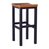
Attach Feet (F) to the Bottom (H) using Cam Lock Screws.

Step 2: Insert Cam Lock Screws

Insert Cam Lock Screws into pre-drilled holes in Top, Seat, Bottom, and Side Panels.

Step 3: Assemble Side Panels and Back/Front Rails

Attach back and front rails, back panel, and side panels using cam locks.

Step 4: Attach Unit to Bottom Panel

Connect the assembled unit to the Bottom (H) using Cam Locks.

Step 5: Attach Hooks to Back Rail

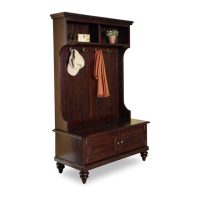
Fasten Hooks to Back Rail (N) using Flat Head Screws.

Step 6: Assemble Side Panel with Back Rails and Panels

Connect Back Rails (L, N) and Back Panels (P, Q) to Side Panel (S).

Step 7: Attach Back Upright and Back Rail

Attach Back Upright (R) and Back Rail (O) to the unit.

Step 8: Attach Shelf and Front Rail

Connect Shelf (B) and Front Rail (J) to the main assembly using Cam Locks.

Step 9: Attach Side Panel T

Connect Side Panel (T) to the unit using Cam Locks.

Step 10: Attach Seat with Wood Screws

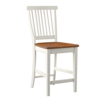
Fasten Seat (G) to the unit using long Wood Screws.

Step 11: Connect Upper and Lower Units

Join the main unit assembly to the structure from Step 4 using Cam Locks.

Step 12: Attach Top, Middle Panel, Doors, and Knobs

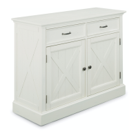
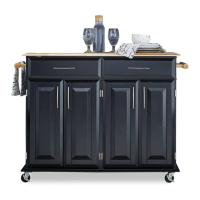
Install Middle Panel (E), Top (A), Doors (U, V) with screws and attach Knobs.

Step 13: Level Unit and Tighten Screws

Adjust levelers for stability and secure the unit with short Wood Screws.

Step 14: Install Tipover Restraint

Secure the unit to the wall to prevent tipping using the provided restraint kit.

Care Instructions

General Care & Usage Warnings

Avoid liquids, direct sunlight, writing on surface, hot objects, rubber placemats, and commercial waxes/polishes.

Cleaning Procedure

Clean with a soft cloth moistened in lukewarm soap and water, then buff with a dry cloth.

Related product manuals