18
Ill. ENGINE
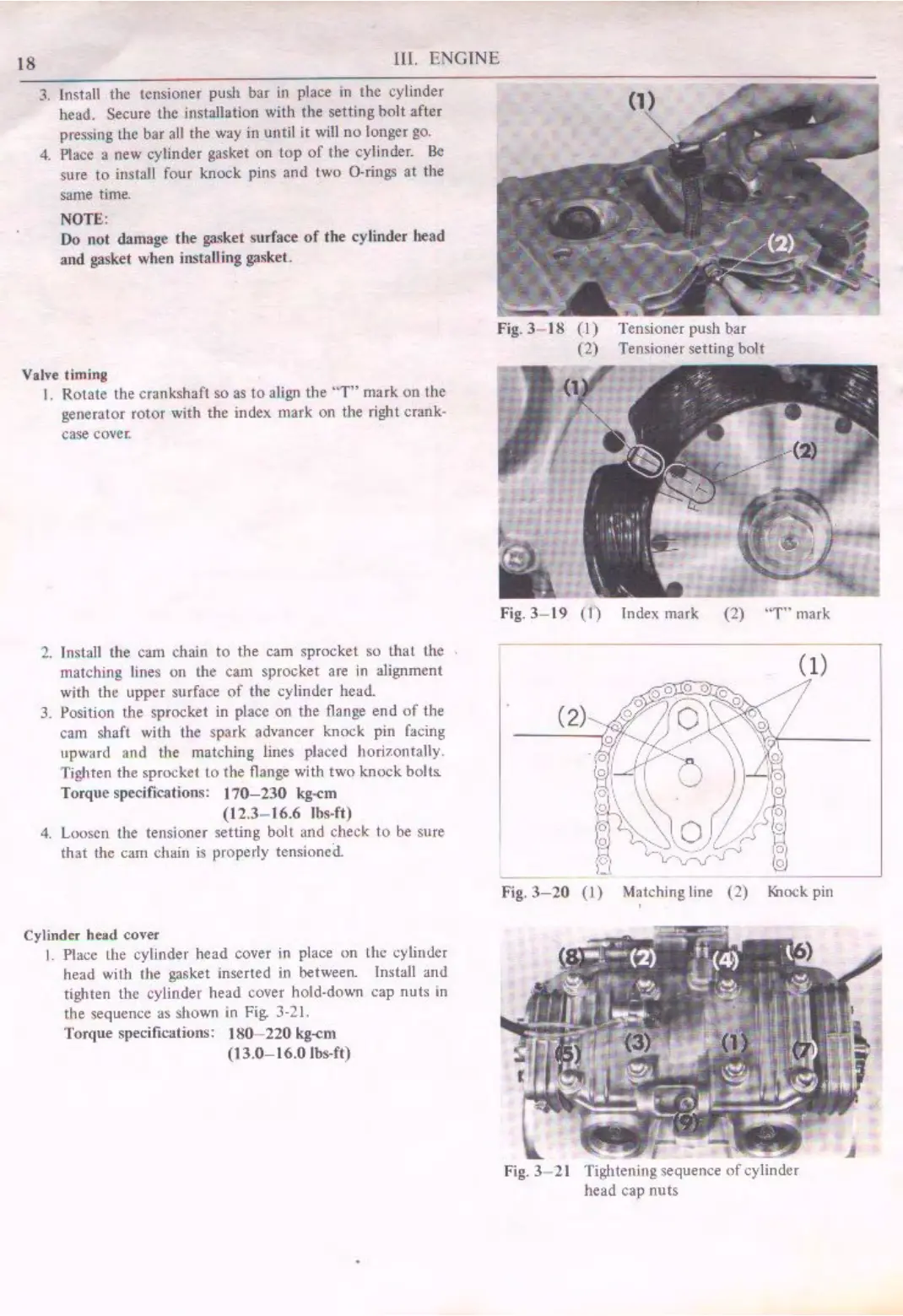
3. Install the tensioner push bar in place in the cylinder
head. Secure the iJ1stallation with the setting
holt
after
pressing
Lhc
bar
all
the way in until
it
will
no
longer go.
4. Place a new cylinder gasket
on
lop
of
the cylinder.
Be
sure
to
insrall four knock pins and
lwo
O·rings
at
the
same time.
NOTE:
Do
not damage
the
gasket surface
of
the cylinder head
and gasket when instaU ing gaskeL
Valve timi.
ng
I. Rotate the crankshaft so
as
to
aligo the
"T"
mark on the
generator rotor with the index
mark
on the right crank-
case
covec
2.
Install the cam chain
to
the
cam sprocket so that the
matching lines
on
the
cam
sprocket are
in
alignment
with the upper surface
of
the cylinder head.
3. Position the sprocket
in
place on the flange
end
of
the
ca,n shaft with the spark advancer knock pin facing
upward and the matching lines placed
hori1.0111ally
.
Tighten the sprocket
LO
the flange with two knock
bolts
Torque specifications:
170-230
kg-cm
(12.3-
16.6
lbs-ft)
4. Loosen the tensioner setting bolt and check
to
be sure
that the
cam
c.;hain
is
pl'Operly
tensioned
Cylinder head cover
I.
Place the cylinder head cover in place
on
the cylinder
head with the gasket inserted in between. Install and
tighten the cylinder head cover hold-down cap
nuts
in
the sequence
as
shown in Fig. J-21.
Torque specifications:
180- 220
kg-cm
(13.0-16.0 lbs-ft)
Fig.
3- 19
(l)
Index mark (2) "T'" mark
(1)
Fig.
3-20
M~tching line (
2)
Knock
pin
Fig.
3-
21



 To Next Page