TV.
FRAME
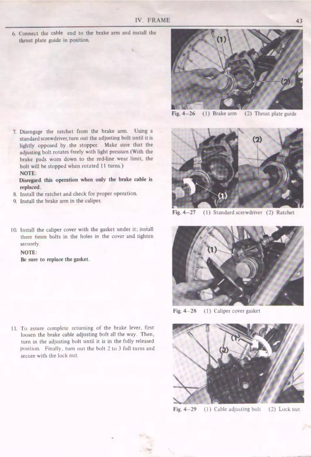
6.
Connect the cahle
end
10 the brake arm antl in.stall the
thrust
plate guide in positiorc
7.
Disengage the
ratchet
from the brake
anll
Using a
standardscrewdriver,turn
out
the adjusting
boll
until
itis
lightly opposed by. the stopper. Make sure
that
the
adjusting
bolt
rotates freely with light prcssure.(With the
brake pads worn down
to
the red-line wear limit, the
bolt
will
be
stopped
when
rotated
11
turns.)
NOTE:
Disregard
this
operation
when
only
the brake cable is
replaced.
8.
Install the ratchet
and
check
for proper operatiorc
9.
Install the brake arm in the caliper.
10.
Install the caliper cover with the gasket
under
it:
insiall
three
6mm
bolts in the holes in the cover
and
tighten
securely.
NOTE:
Be
sure
to
replace the gasket.
11
.
To
assure complete returning
of
the brake lever, first
loosen the brake cable adjusting
bolt
all the way.
Then,
turn
in the adjusting
holt
until
it
is
in
the fully released
pusitiurc Finally,
turn
out
the bull 2
tu
3 full turns
and
secure
with
the lock nut.
....
43
Fig.
4-26
(I)
Brake arm
(2)
Thrust
plate guide
Fig.
4-27
(I)
Standard
screwdriver
(2)
Ratchet
fig. 4
21!
( I) Caliper cover gasket
Fig.
4 -
29
(I)
Cable adjusting bolt (2) Lock.
nut
 Loading...