GX240 • GX270 • GX340 • GX390 (UT2/RT2) Technical Manual
12 © 2010 American Honda Motor Co., Inc — All Rights Reserved
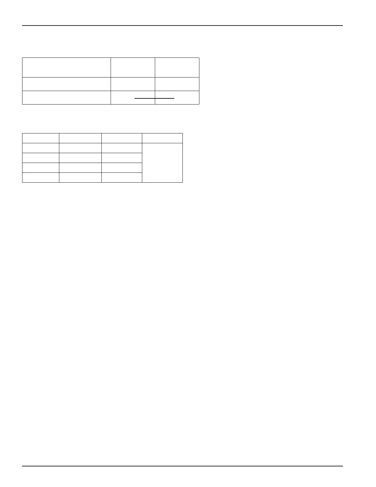
Manual start
Use a two-position engine switch with continuity between its terminals as shown.
Charging Coil Selection
Four types of coils are available:
The 1A and 3A coils are only suitable for recharging a starting battery. Use the 10A or 18A coils when powering
accessories.
Lamp Coil Kit (optional)
Three types of lamp coils are available: 6v –25w, 12v –15w, 12v –25w. Two coils can be installed in parallel to provide
12V-50W, if no charging coils are applied. Use parallel connector (No. 32105-ZE1-000) to connect two coils in parallel.
A single coil (12v-25w) can be used in combination with the 3A charge coil as required.
Oil Alert
®
System (optional)
The Oil Alert System uses a float type switch located inside the crankcase. When the engine oil level falls below a safe
operating level, the float falls and the circuit is completed through the control box, grounding the primary side of the
ignition coil. The Oil Alert System is only recommended for use on equipment that is stationary while operating.
Wiring Precautions
• Connect the battery positive (+) cable to the positive terminal of the starter solenoid.
• Connect the battery negative (–) cable to the engine crankcase or engine frame mounting bolt.
• Do not route the battery cables on or near any hot, moving, or rotating parts, or sharp edges. Keep the battery
cables and electrical wires away from the fuel line.
• Protect positive electrical connections with a cover or insulation.
Wire Color
EXT+
(Red)
EXT –
(Black)
Switch Position
OFF
ON {{
Coil Output (A) Regulated RPM
1A 0.9 No
3,600
3A 2.7 No
10A 9.5 Yes
18A 17.0 Yes
 Loading...