FUEL SYSTEM (Programmed Fuel Injection)
6-30
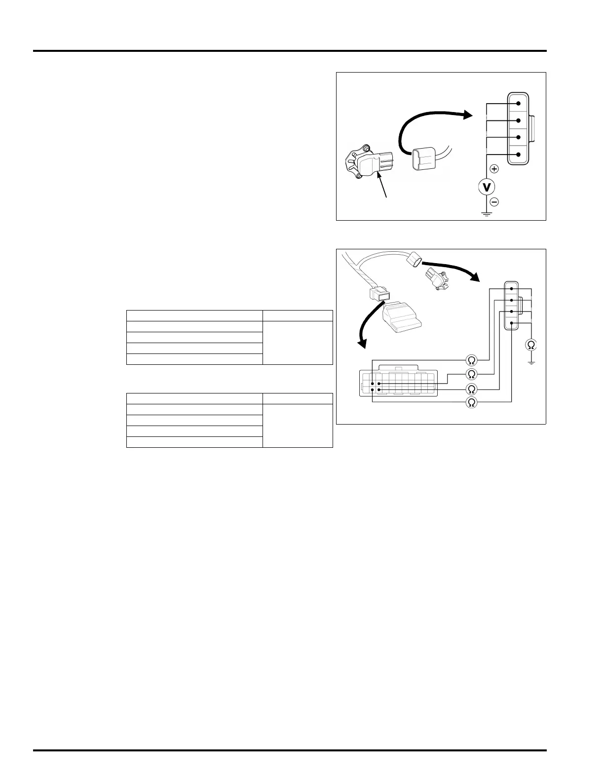
4. IACV Input Voltage Inspection
Turn the ignition switch "ON".
Measure the voltage between the IACV 4P con-
nector of the wire harness side and ground.
Is the voltage within 1.8 – 2.2 V?
YES – • Loose or poor contact on the ECM
connectors.
• Intermittent failure.
NO – GO TO STEP 5.
5. IACV Circuit Continuity Inspection
Turn the ignition switch "OFF".
Disconnect the ECM 33P connector.
Check for continuities between the IACV 4P con-
nector and the ECM 33P connector of the wire
harness side.
Check the continuities between the IACV 4P con-
nector of the wire harness side and ground.
Are the above inspections normal?
YES – Replace the ECM with a new one, and recheck.
NO – • Open or short circuit in Light green/
Red wire.
• Open or short circuit in Gray/Red
wire.
• Open or short circuit in Brown/Red
wire.
• Open or short circuit in Black/Red
wire.
CONNECTION: Light green/Red (+) – Ground (–)
Gray/Red (+) – Ground (–)
Brown/Red (+) – Ground (–)
Black/Red (+) – Ground (–)
STANDARD: 1.8 – 2.2 V
CONNECTION STANDARD
Light green/Red
–
Light green/Red
Continuity
Brown/Red – Brown/Red
Black/Red – Black/Red
Gray/Red – Gray/Red
CONNECTION STANDARD
Light green/Red – Ground
No continuity
Brown/Red – Ground
Black/Red – Ground
Gray/Red – Ground
33P CONNECTOR
4P CONNECTOR
ECM
IACV
 Loading...