BRAKE SYSTEM
17-16
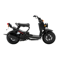
Turn the adjuster until the edge surface of the
knocker seats on the edge surface of the master cyl-
inder body.
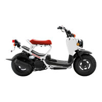
Check that there is no gap between the knocker pin
and the end of the slot of the knocker joint.
If there is any gap, turn the adjuster until there is no
gap between the knocker pin and the end of the slot
of the knocker joint.
After adjustment, hold the adjuster and tighten the
lock nut to the specified torque.
After tightening the lock nut, check that there is no
gap between the knocker pin and the end of the slot
of the knocker joint.
Apply rear brake lever several times and check that
the distance between the edges has not been
changed after applying the brake.
Recheck the edge surface of the knocker seats on
the edge surface of the master cylinder body.
Install the following:
– Rear handlebar cover (page 3-7)
– Front handlebar cover (page 3-6)
Check the brake operation by applying the front
brake lever.
BRAKE EQUALIZER
REMOVAL
Remove the front handlebar cover (page 3-6).
Disconnect the connecting cable (page 17-11).
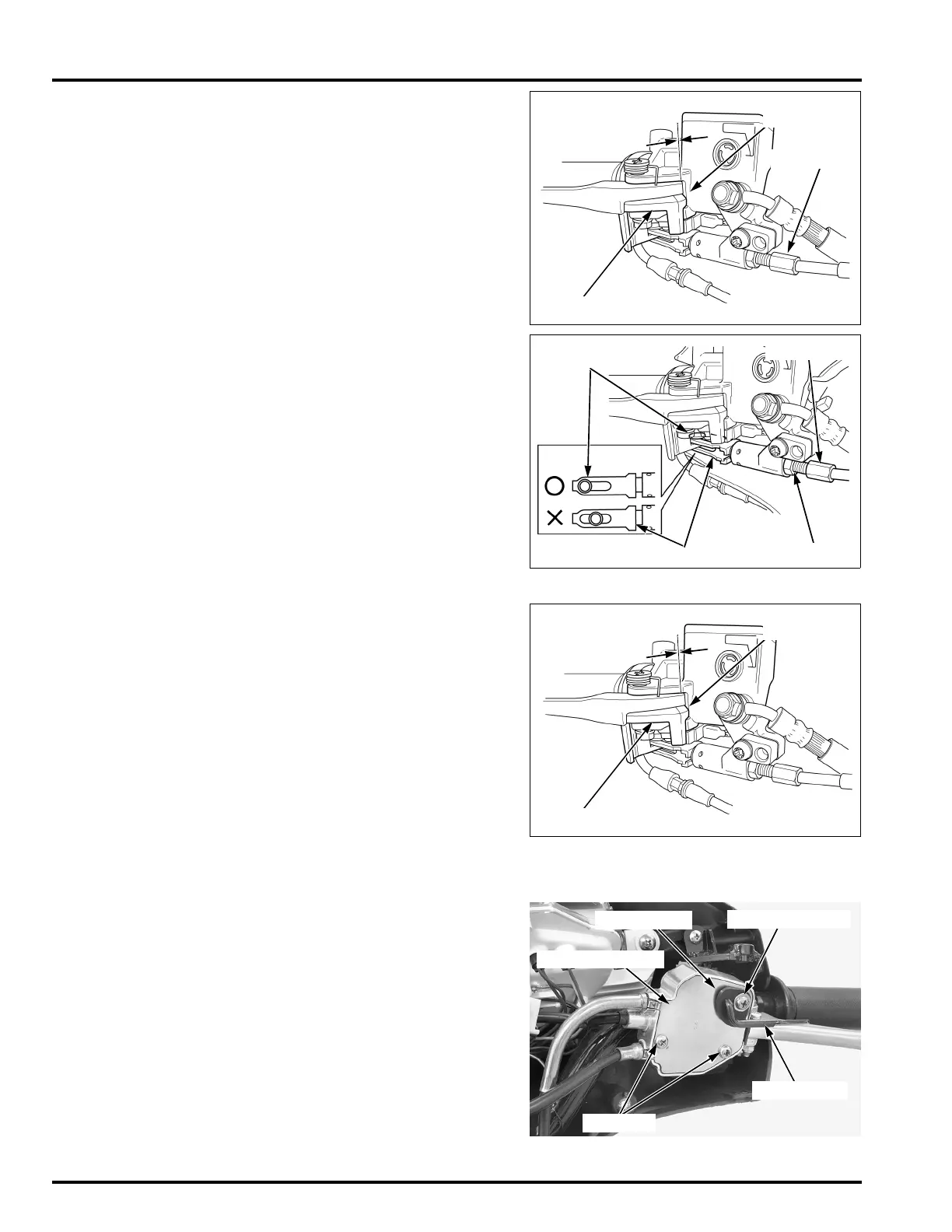
Remove the bracket cover special screw and the set
rubber.
Remove two bracket cover screws.
Remove the bracket cover while holding the lock
lever.
KNOCKER
ADJUSTER
INSPECTION
POINT
TORQUE: 6.4 N·m (0.65 kgf·m, 4.7 lbf·ft)
LOCK NUT
ADJUSTER
KNOCKER JOINT
KNOCKER PIN
SPECIAL SCREW
SCREWS
BRACKET COVER
SET RUBBER
LOCK LEVER
 Loading...