FUEL SYSTEM (Programmed Fuel Injection)
6-51
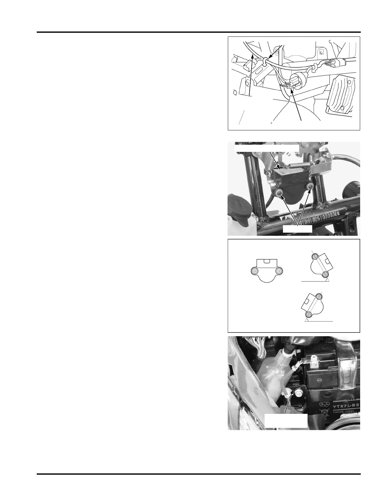
Connect the bank angle sensor 6P (Black) connector
and clamp the bank angle sensor wire.
Install the body cover (page 3-9)
SYSTEM INSPECTION
Turn the ignition switch "OFF".
Remove the following:
– Front center cover (page 3-4)
– Luggage box (page 3-8)
Remove the two screws and bank angle sensor.
If you perform this
test, turn the igni-
tion switch "OFF",
then turn the igni-
tion switch "ON".
Place the bank angle sensor in normal position as
shown, and turn the ignition switch "ON". The bank
angle sensor is normal if the engine stop relay
clicks, which indicates that circuit is closed.
Incline the bank angle sensor approximately 49 ± 4°
to the left or right while the ignition switch is "ON".
The bank angle sensor is normal if the engine stop
relay clicks, which indicates that circuit is opened.
If the bank angle sensor does not operate, refer to
the circuit inspection (page 6-52), if the circuit
inspection is normal, replace the bank angle sensor
with a new one and recheck.
6P (Black) CONNECTOR
CLAMP
BANK ANGLE
SENSOR WIRE
Do not disconnect
the bank angle sen-
sor connector dur-
ing inspection.
49 ± 4° BANK ANGLE POSITION
(approximately) 49 ± 4°
Normal
position
ENGINE STOP
RELAY
(approximately) 49 ± 4°
 Loading...