MAINTENANCE
4-19
Remove the front handlebar cover (page 3-6).
Check the rear brake lever freeplay (page 4-17).
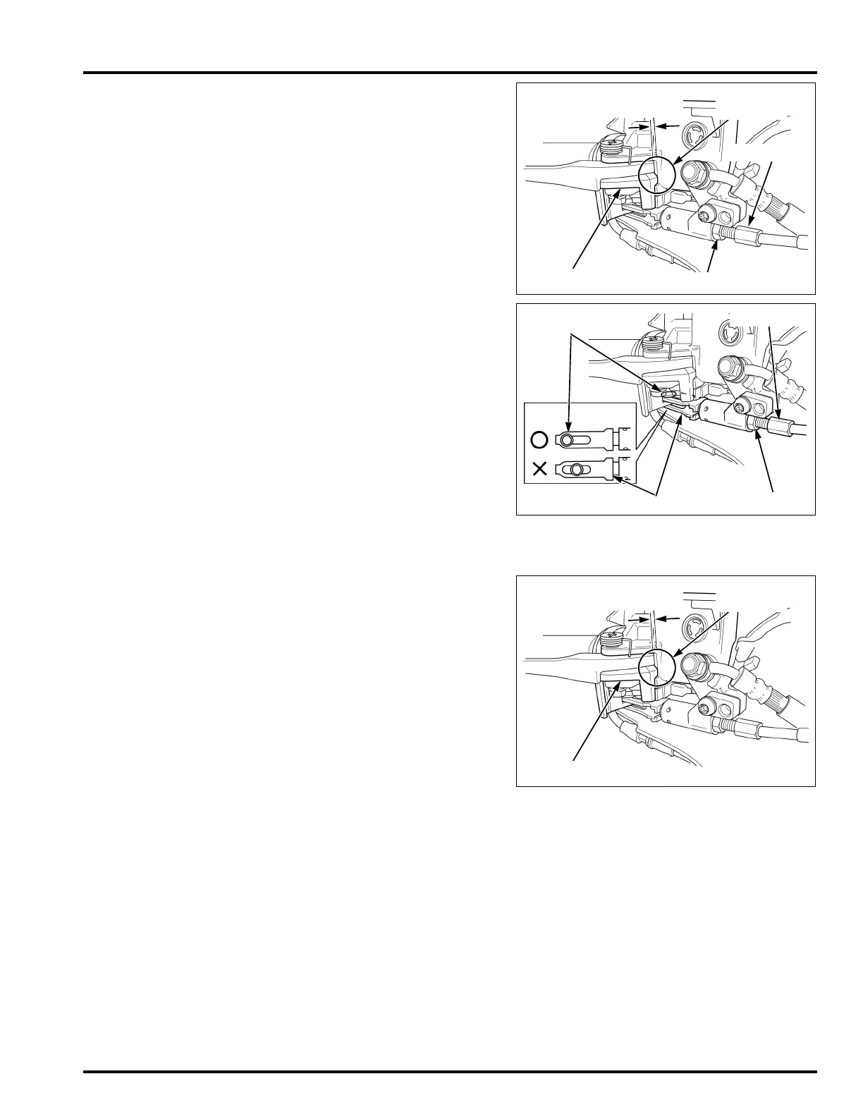
Measure the distance between the edge surface of
the knocker and the edge surface of the master cyl-
inder body with the feeler gauge.
If the distance exceeds the standard, adjust the con-
necting cable as follows:
Loosen the lock nut and turn the adjuster until the
distance between the edge surfaces is within stan-
dard.
Check that there is no gap between the knocker pin
and the end of the slot of the knocker joint.
If there is any gap, loosen the lock nut and turn the
adjuster until there is no gap between the knocker
pin and the end of the slot of the knocker joint.
After the adjustment, hold the adjuster and tighten
the lock nut to the specified torque.
After tightening the lock nut, check the rear brake
lever freeplay again (page 4-17) and, check that
there is no gap between the knocker pin and the end
of the slot of the knocker joint.
Apply rear brake lever firmly about 10 times so to
fit the brake cables. Check that the distance between
the edges has not been changed after applying the
brake.
Recheck that the distance between the edge surface
of the knocker and the edge surface of the master
cylinder body is within standard.
Recheck the combined brake system (page 4-18).
If the combined brake system adjustment is normal,
but the front wheel rotates abnormally, check for
other malfunction parts.
Install the front handlebar cover (page 3-6).
STANDARD: 0 – 0.1 mm (0 – 0.004 in)
KNOCKER
0 - 0.1 mm
(0 - 0.004 in)
LOCK NUT
ADJUSTER
Inspection
point
TORQUE: 6.4 N·m (0.65 kgf·m, 4.7 lbf·ft)
STANDARD: 0 – 0.1 mm (0 – 0.004 in)
LOCK NUT
ADJUSTER
KNOCKER JOINT
KNOCKER PIN
KNOCKER
0 - 0.1 mm
(0 - 0.004 in)
Inspection
point
 Loading...