ELECTRIC SHIFT PROGRAM (ESP : FE/FPE
mod
els)
DTC 42
-1
(GEARSHIFT SWITCH
CIRCUIT)
NOTE
Before starting the troubleshooting , check
for
l
oose
or
poor
contact
of
the following connectors , and recheck
the
DTC
(page
23-14).
-
handlebar
switch 1
4P
(Green)
-
PCM
SP
(Black)
1.
Gearshift
Switch
Inspection
Check
the gearshift switch status
with
Ihe
HOS
data
list menu.
UP
--
DOW
N!
I
~
"Up"
ON
3.64 - 4.08 V
1.
76
- 2.09 V
---
"
Down
" ON
1.
76
- 2.09 V
3.64
-4.08
V
4.0 - 4.99 1
,
Both
ON
' 4.0 4.99 V
Both OFF
I
O_D
.
99V
O-O
.
g9V
Is
the
gearshift
switch
status
normal?
YES - Intermittent failure
NO
- GO TO STEP 2.
2.
Gearshift
Switch
I
nspection
at
Handlebar
Switch
Connector
Turn
the ignition switch
OFF
.
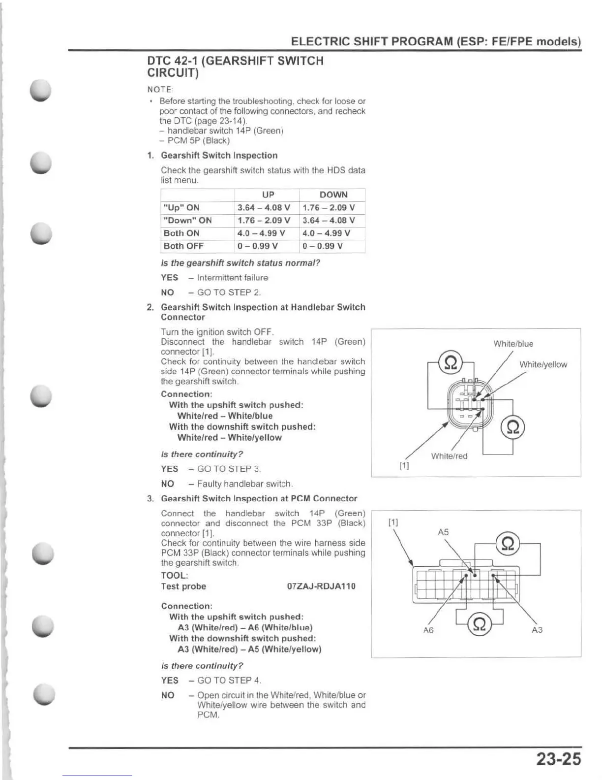
Disconnect Ihe handlebar switch 14P (Green)
connector [1].
Check for continuity between the handlebar switch
side
14P (Green) connector terminals while pushing
the gearshift switch.
Connect
i
on
:
With
the
upshift
switch
pushed
:
White
/red -
White
/
blue
With
the
downshift
switch
pushed
:
White
/red -
White
/
yellow
Is
there
continuity
?
YES -
GO
TO
STEP
3.
NO - Faulty handlebar switch .
3.
Gearshift
Switch
I
nspection
at PCM
Connector
Connect the handlebar switch 14P (Green)
conneclor and disconnect the PCM 33P (Black)
connector [11.
Check for continuity between the wire harness side
PCM 33P (Black) connector terminals while pushing
the
gearshift switch.
TOOL
:
Test
probe
07ZAJ-ROJA110
Connection
:
With
the
upshift
switch
pushed:
A3
(White/red) -
A6
(White/blue)
With
the
downshift
switch
pushed
:
A3 (White/red) -
AS
(White/
yellow)
/s
there
con
t
inui
t
y?
YES -
GO
TO
STEP 4.
NO - Open circuit
in
the Whitelred, White/blue or
White/yellow wire between the sWitch and
PCM.
Whltelblue
Whi
te/yellow
White/
red
111
111
A5
Q
A6
A3
23-25






 To Next Page