EasyManua.ls Logo

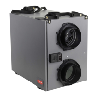
Honeywell Home VNT5200E1000 User Manual

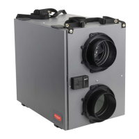
Honeywell Home VNT5200E1000
88 pages
To Next Page IconTo Next Page
Page #1 background imageLoading...
Page #1 background image
Tools required to install ERV/HRV
Aluminum foil tape (UL181B)
Standard screwdriver
Crescent wrench
Hex driver (1/4 in.)
Accessories (not included)
6 in. Dia. insulated duct (VNT5150, VNT5200,
VNT6150 & VNT6200)
6 in. Dia. duct (VNT5150, VNT5200)
Two 6 in. Dia. weather hoods (VNT5150, VNT5200 ,
VNT6150 & VNT6200)
5in.Dia.insulatedexduct(VNT5070)
5in.Dia.exduct(VNT5070)
6in.Dia.matrixhood,50063805-009(VNT5070)*
* 6 in. to 5 in. reducer required
D1
A3
E
A1 A2 B C
ERV/HRV VNT5150H1000, VNT5150E1000 or
VNT6150H1000
ERV/HRV VNT5200H1000, VNT5200E1000 or
VNT6200H1000
ERV/HRVVNT5070H1000orVNT5070E1000
Heat/Energy Recovery Core (1)
Filter (2)
Round Duct Collars (4) (VNT5150 and VNT5200,
VNT6150 & VNT6200)
OvalDuctCollars(VNT5070)
Installation Kit (flex included with 5150 and 5200,
VNT6150 & VNT6200)
WallMountBracket(VNT5070)
Optional Controls: 1 - Prestige IAQ Kit, 2 - True IAQ,
3 - Dehumidistat H8908D, 4 - Prestige IAQ,
5 - 20/40/60 Minute Boost Control,
6 - W8150 Ventilation Control
7 - Vent Boost Remote, 8 - VisionPRO Wi-Fi
A1
E
F
D1
D2
A2
A3
B
C
G
F
D2
OPTIONAL CONTROLS SOLD SEPARATELY
G8
G3
G6 G7
G5
G4
G1 G2
PROFESSIONAL INSTALLATION GUIDE.
GUIDE D’INSTALLATION PROFESSIONNELLE.
69-2480EF-17
TrueFRESH™ ERV/HRV Ventilation Systems
Systèmes de ventilation V/VRC TrueFRESH
INCLUDED IN THIS BOX

Questions and Answers:

Honeywell Home VNT5200E1000 Specifications

General IconGeneral
BrandHoneywell Home
ModelVNT5200E1000
CategoryFan
LanguageEnglish

Summary

TrueFRESH ERV/HRV Ventilation Systems

Included in This Box

Lists components included in the product packaging.

Optional Controls

List of optional external control accessories available.

Installation Checklist

Tools Required

List of tools needed for installation.

Accessories (Not Included)

List of necessary accessories not supplied with the unit.

About the ERV/HRV Ventilation System

Benefits

Outlines the advantages and features of the ventilation system.

Determining Your Ventilation Needs

ASHRAE 62.2 Ventilation Standard

Provides sizing guidelines based on home area and bedrooms.

Air Change Per Hour (ACH) Method

Explains calculation for determining ventilation requirements.

Specifications

Physical Specifications

Details unit dimensions, weight, and core dimensions.

Electrical Ratings

Lists input voltage, current, and power output.

External Control Options

Prestige IAQ Kit

Description of the Prestige IAQ Kit control.

VisionPRO or Prestige

Overview of VisionPRO and Prestige thermostat controls.

Install to Fit Your Application

Independent System

Describes a basic, standalone installation setup.

Exhaust at the Source and Supply in the Return

Details integrating with a forced air system's return duct.

Exhaust and Supply in the Return

Explains another method of integrating with forced air systems.

Installation Steps

Installation Kit and Area

Lists kit components and guides on selecting installation location.

Unit Hanging Procedures

Step-by-step instructions for hanging specific unit models.

Unit Mounting Procedures

Specific mounting procedures for the VNT5070 model.

Ducting Connection Steps

Instructions for connecting flexible ductwork.

Condensate Drain Line Installation

Guide to connecting the condensate drain system.

Power and Exterior Hoods

Steps for connecting power and mounting outside hoods.

Optional Matrix Hood Installation

Details for installing an optional matrix hood.

Automated Defrost

Wiring

Terminal Description

Identifies and explains the unit's wiring terminals.

Wiring with Remote Controls

Wiring diagrams for different control modes.

Controls Wiring

Diagrams for connecting various IAQ controls to the system.

Prestige Thermostat

Wiring diagram for Prestige thermostat integration.

VisionPRO IAQ Equipment Interface Module

Wiring instructions for the VisionPRO IAQ module.

General Ventilator Wiring (not interlocked)

Wiring for standalone unit operation.

General Ventilator Wiring Interlock Wiring with Equipment Fan

Wiring for interlocked operation with HVAC systems.

TrueIAQ

Wiring diagram for the TrueIAQ control device.

Dehumidistat

Wiring diagram for a dehumidistat controller.

Honeywell 20/40/60 Minute Boost Control Timer

Wiring for a boost timer accessory.

Control Panel

Speed Control Functions

Explains the selector switch and speed control buttons.

Speed Control used as a Mode Control

How the selector switch functions as a mode selector.

Speed Control used as a Balancing Control

Use of the control for motor speed balancing.

Balancing Steps

Pre & Post Balancing Steps

Procedures for airflow measurement and balancing.

Balancing Reset

Checkout

Airflow Measurements - VNT5070 only

Maintenance

Filters

Instructions for cleaning or replacing filters.

Inside the Unit

Guidance on cleaning the interior of the unit.

Cleaning Steps

Troubleshooting

No Power to Unit

Diagnosing and resolving power-related issues.

Motor Not Functioning

Troubleshooting motor operational problems.

HRV/ERV Operating Only on High Speed

Addresses issues with high-speed operation and communication.

Yellow Blinking LED on Speed Controller

Diagnosing faults indicated by the speed controller LED.

Honeywell OS and Parts List

Parts List

A detailed list of all available replacement parts.

Parts Illustration (VNT5150, VNT5200, VNT6150 & VNT6200)

Parts Illustration (VNT5070)

5-Year Limited Warranty

Related product manuals