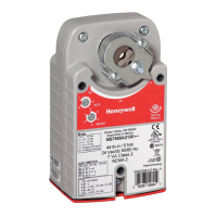
3 NM, 5 NM SERIES SPRING RETURN DIRECT COUPLED ACTUATORS
62-0274—07 10
Fig. 23. Override to full close.
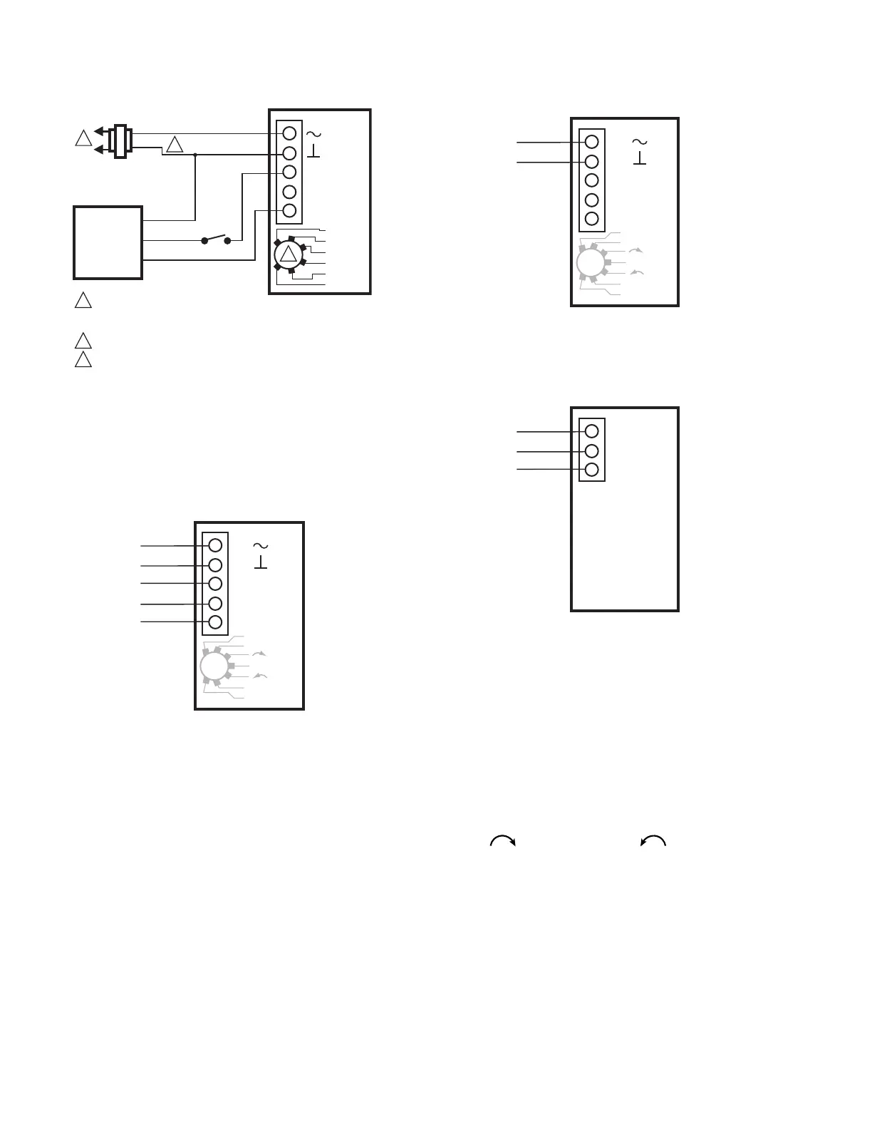
Typical Wiring With Cable
See Fig. 24 through 26 for wiring actuators with cables
(whips). See Fig. 9 through 23 for typical wiring details for
actuators without cables (whips).
Fig. 24. Cable wiring for floating and modulating (0/2-10
Vdc) control, MS7505W series.
Fig. 25. Cable wiring for low voltage, two-position control,
MS8105W series.
Fig. 26. Switch only models.
End Switches
Some models include an adjustable end switch. For wiring
details, see Fig. 11.
CHECKOUT
Modulating/Floating Operation
1. Mount actuator for required application (either clock-
wise or counterclockwise rotation to open
the damper).
2. Connect power to terminals 1 and 2. (See Fig. 11 and
Table 2.)
3. Set “Mode Select” dial to desired control signal.
(See Fig. 4.)
4. Apply control signal for actuator full open or full closed
position. (See Fig. 11 and Table 2.)
a. (0)2-10 Vdc: apply 10 Vdc signal to terminal 3.
b. 10-(0)2 Vdc: apply (0)2 Vdc signal to terminal 3.
c. (0)4-20 mA: apply 20 mA signal to terminal 3.
d. 20-(0)4mA: apply (0)4 mA signal to terminal 3.
e. Floating: apply 24 Vac to appropriate 0°-90° (3) or
90°-0° (4) terminal.
5. Actuator drives to full open or full closed position.
ACTUATOR
0/2 TO 10 VDC
PROPORTIONING
CONTROLLER
24 VAC
1
1
2
3
2
LINE VOLTAGE POWER SUPPLY.
PROVIDE DISCONNECT MEANS AND
OVERLOAD PROTECTION AS REQUIRED.
24 VDC SUPPLY ACCEPTABLE.
SET SWITCH TO MODULATING.
V
FEEDBACK
–
+
FEEDBACK
5
4
3
1
2
2-10 VDC
10-2 VDC
0-10 VDC
10-0 VDC
Fltg, fwd
Fltg, rev
3
SPST
M27828
0°-90° OR +
90°-0° OR N/A
M28934
ACTUATOR
BLU
BRN
WHT
BLK
RED
5
4
3
1
2
Dir
Service/Off
Rev
2... 10 V
0... 10 V
10... 0 V
10... 2 V
V
0° -90° OR +
FEEDBACK
90° -0° OR N/A
M28935
ACTUATOR
BLK
RED
5
4
3
1
2
Dir
Service/Off
Rev
2... 10 V
0... 10 V
10... 0 V
10... 2 V
V
M28973
ACTUATOR
PPL
YEL
ORG
3
1
2
 Loading...


