EN1R-9175 0908RA-NE 4
Manufactered for and on behalf of the Environmental and Combustion Controls Division of Honeywell Technologies Sàrl, Z.A. La Pièce 16, 1180 Rolle, Switzerland by its Autorized Representative:
Automation and Control Solutions
Combustion Controls EMEA
Honeywell BV
Phileas Foggstraat 7
7821 AJ Emmen
The Netherlands
Tel.: +31 (-)591 695911
Fax: +31 (-) 591 695200
http://ecc.emea.honeywell.com
MODUPLUS® TRADELINE
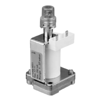
Mounting Moduplus® Tradeline on gas valve. (see fig 3)
• Verify that all parts are present in Moduplus® tradeline
box (1 moduplus®, 1 gasket, 2 screws, 1 cap)
• Shut off gas and power supply, disconnect Moduplus® coil
wiring and disconnect pressure feedback connection (if
applicable)
• Remove old Moduplus® regulator and discard gasket.
Place new gasket at the bottom side of Moduplus®.
Orientation of the gasket must be as indicated in figure 3!
Push gasket over the small bosses (A), so that the bosses
show fully through the gasket.
• Mount Moduplus® on the gas valves.
The electrical connectors of the Moduplus® coil must face
the coil of the gas valve. (see fig. 2)
The 2 mounting screws must be fastened to 3 Nm.
• Switch on gas and power supply, energize operator of gas
valve. Check for outerwall leakage around perimeter of
Moduplus®.
• Adjust maximum and minimum pressure setting according
chapter ‘Adjustment, Checkout and Maintanance’
• Place cap over adjustment screws until it snaps over
protruding circular boss and reconnect pressure feedback
connection (if applicable)
Fig. 3. Moduplus® Tradeline parts
 Loading...