The 7866 Triple Range Digital H₂ and CO₂ Analyzer/Indicator and Gas Sampling Panel is a device designed for the measurement of hydrogen (H₂) and carbon dioxide (CO₂) in various applications. It provides three measurement ranges, making it versatile for different gas concentrations. The device consists of a sensing unit and a digital controller, with an optional gas sampling panel for specific applications.
Function Description
The 7866 analyzer operates on the principle of thermal conductivity. The sensing unit contains two sets of thermistors: one for the reference cell and one for the measuring cell. These thermistors are arranged in a Wheatstone bridge circuit. The high-purity hydrogen thermistor is mounted in each cell, and the matched thermistors form the active arms of the bridge circuit. The unbalanced current in the bridge provides a means of measuring the relative ability of the sample and reference gases to conduct heat away from their respective thermistors to the cell wall, which is held at a constant temperature. The cells in which the thermistors are mounted are dual-ended, allowing the sample gas to enter only by diffusion, minimizing the effect of sample flow variations. The entire cell-block assembly is maintained at a constant optimum temperature through two heaters and a control thermistor.
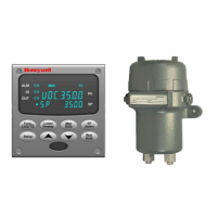
The digital controller provides a current output and a digital display of the measured gas percentage, with up to two alarm circuits. The alarm limits are set using the integral keyboard on the front of the instrument. The SETPOINT SELECT key is used to select the appropriate range. The second current output is available and will supply a value for the selected range data that can be retransmitted to a remote indicator. The unit also provides access to the calibration settings for each range. The zero and span settings are entered using the group prompt CALIB. The current prompt RANGE n (0, 1, 2, or 3), Zero and Span are "live" readings, and the FUNCTION key is pressed, which means that display value is captured. The increment/decrement keys can then be used to change the desired value. These values are normally secured from inadvertent or unauthorized tampering using a four-digit security code.
Important Technical Specifications
- Accuracy: ± 2% of span (output signal) at reference conditions for binary gas mixtures.
- Linearity: Within ± 2% of span for most standard ranges. If linearity exceeds ± 2%, a correction curve is supplied with the analyzer.
- Meter Accuracy: Digital indication: ± 0.1%.
- Repeatability: Short term: ± 0.3% of span.
- Reproducibility: 24 hour: ± 1% of span.
- Response Time:
- For H₂: 90% less than 1 second; 63%: 13 seconds; 99%: 40 seconds.
- For CO₂ (initial): 90% less than 2 seconds; 63%: 24 seconds; 90%: 45 seconds; 99%: 80 seconds.
- Maximum Drift: Zero: ± 2% of span per week maximum; Span: ± 2% of span per week maximum.
- Ambient Temperature Influence: At sensing unit: Depends on range; typically less than 1% F.S. over entire temperature range.
- Atmospheric Pressure Influence: ± 0.01% of span per inch H₂O (± 0.05% of span per mm Hg).
- Sample Flow Rate Influence: Less than ± 0.5% of span over flow range of 0.2 to 4 cfh (100 to 2000 cc/min).
- Line Voltage Influence: Maximum 0.02% of span for each 1% change of line voltage.
- Measuring Range: Triple Range Analyzer: Three ranges—Range 1 measures CO₂ in Air, Range 2 measures H₂ in CO₂, and Range 3 measures H₂ in Air.
- Output Ranges: 0-20 mA maximum load: 800 ohm; 4-20 mA maximum load: 800 ohm.
- Alarm Outputs: One or two alarms are available; each uses an SPDT electromechanical relay.
- Reference Gas Requirements: Triple Range Analyzer: The triple range H₂ and CO₂ analyzer requires flowing air as the reference gas, 0.02 – 0.2cfh (10 – 100cc/min), 2 psig (13.79kPa) max. Sensor outlets must vent to atmospheric pressure.
- Power Requirements: Control Unit only: Universal supply 90 Vac to 264 Vac (consumption 18 VA maximum) or 24 Vac/dc (consumption 12 VA maximum); 50 Hz to 60 Hz.
- Physical Specifications:
- Sensing Unit: 8.5 kg (18-3/4 lb.) Dimensions: Approximately 150 mm x 150 mm x 325 mm (6 in. x 6 in. x 12-3/4 in.).
- Control Unit: 1.3 kg (3 lb.) Dimensions: Bezel: 96 mm H x 96 mm W (3.78" H x 3.78" W); Case: 92 mm H x 92 mm W x 192 mm D (3.62" H x 3.62" W x 7.55" D).
- Communications: RS422/485 Modbus RTU Communications (Optional), Ethernet TCP/IP Communications (Optional), Infrared Communications (Standard).
Usage Features
- Digital Display: The controller features an upper display (7 characters) for process variable or adjustable decimal point, and a lower display (8 characters) for parameter values or selection.
- Keypad Interface: The controller has a keypad with buttons for "Setup," "Func Loop 1/2," "SP Select," "Lower Display," "Man Auto," and "Run Hold" to navigate menus, adjust parameters, and control operations.
- Configuration: The device allows for extensive configuration through its "Set Up Mode," including security settings, analyzer range type, current output settings, alarm set points, and communication parameters (IR, RS-485, Ethernet).
- Calibration: The analyzer supports calibration for each range (CO₂ in Air, H₂ in CO₂, H₂ in Air) by connecting the appropriate gas source and adjusting zero and span values. Remote indicator input calibration and factory-set input calibration are also supported.
- Security Lockout: A security lockout feature prevents unauthorized changes to settings. Different levels of lockout can be configured.
- Alarm Management: The device provides two alarms with adjustable set points and hysteresis. These alarms can be configured to trigger based on measured gas concentrations.
- Process Instrument Explorer Software (P.I.E.): This software allows users to configure, upload, and download configurations from the controller to a PC. It supports various communication types, including infrared, RS 485, and Ethernet.
- Gas Sampling Panel (Optional): The 7872 Gas Sampling Panel is an optional accessory that provides a complete system for delivering sample gas to the analyzer. It includes flowmeters, regulators, and bypass valves to ensure accurate and stable sample delivery.
Maintenance Features
- Routine Maintenance: Regular checks of gas flow rate and sampling system are recommended.
- Sensing Unit Disassembly: The sensing unit can be disassembled for maintenance, including removal of the threaded cover, turning the circuit board counterclockwise, and loosening the set screw.
- Circuit Board Replacement: The plastic sensor assembly can be removed to access and replace the circuit board.
- Cell-Block Assembly: The cell-block assembly can be removed for maintenance, which involves unsolder-ing the interconnecting wires and removing screws.
- Repacking: When repacking for shipment, the sensor assembly inlet and outlet ports should be taped to prevent packing material from clogging.
- Spare Parts: A list of recommended spare parts is provided, including O-rings, thermistors, and flame arrestors.
- Troubleshooting Guide: A comprehensive troubleshooting section helps identify and resolve common issues, including problems with display, span, flow rate, output signal, and alarm malfunctions. It provides possible causes and recommended checks for each symptom.
- Recalibration: A routine procedure for checking calibration is presented, with instructions for coarse zero adjustment.
- Resistance Check: Instructions are provided for measuring and checking the resistance of thermistors and other components to diagnose issues.
- Wiring and Piping Checks: Regular checks of all wiring and piping connections are recommended to ensure they are tight and properly installed.
- Explosion-Proof Requirements: Specific instructions are given for maintaining the explosion-proof integrity of the sensing unit, including ensuring the threaded cover is properly secured and all conduits are sealed.