11
EN2R--9023 9705R0--NE
CALCULATIONS
General
The maximum allowable leak--rate (according the EN676 and
EN746--2) is 0,1 % of the maximum burner capacity. The test
time necessary to detect a falling valve is a function of:
− inlet pressure
− test volume
− burner capacity.
When the volume between two safety--valves is bigger it
takes more time (in case of a leaking valve) to change the
status of the gas pressure switch. The correct OS--number
for the A4021A can be selected after calculating the
appropriate test--times for the intended application.
The switching point of the pressure--switch is set to 50 % of
the maximum inlet pressure.
ThetestperiodTpiscalculatedfromtheinletpressurePi,the
test volume Vp ( see Table 4.) and maximum burner capacity
Qm, in formula:
Tp ≡
2xPixVp
Qm
[s]
Pi = inlet pressure [mbar]
Vp = test volume [ dm
3
],seealsoTable4.
Qm = burner capacity [dm
3
/h]
Table 4. Volumes in dm
3
for UGV valves
Vp
with length of
pipe L (including V1 and V2)
DN
Length between valves (m)
0 0,5 1 1,5 2 per
extra
meter
10T 0.06 0.10 0.14 0.18 0.22 0.08
15T 0.06 0.15 0.24 0.33 0.42 0.18
20T 0.12 0.28 0.43 0.59 0.74 0.31
25T 0.19 0.44 0.68 0.93 1.2 0.49
32T 0.69 1.1 1.5 1.9 2.3 0.80
40T 0.71 1.4 2.0 2.7 3.3 1.3
50T 1.3 2.3 3.3 4.2 5.2 2.0
65T 2.7 4.4 6.0 7.7 9.3 3.3
80T 2.9 5.4 7.9 10 13 5
65F 3.2 4.9 7.5 8.2 9.8 3.3
80F 4.4 6.9 9.4 12 14 5.0
100F 6.5 10.5 14.4 18 22 7.9
NOTE: T=Thread
F=Flange
V
0m
= volume of 2 valves with L= 0 m
IMPORTANT
ThetotalvolumeVphastobecalculatedwithall
volumes between the tested valves: internal
volumes of valves and all pipes
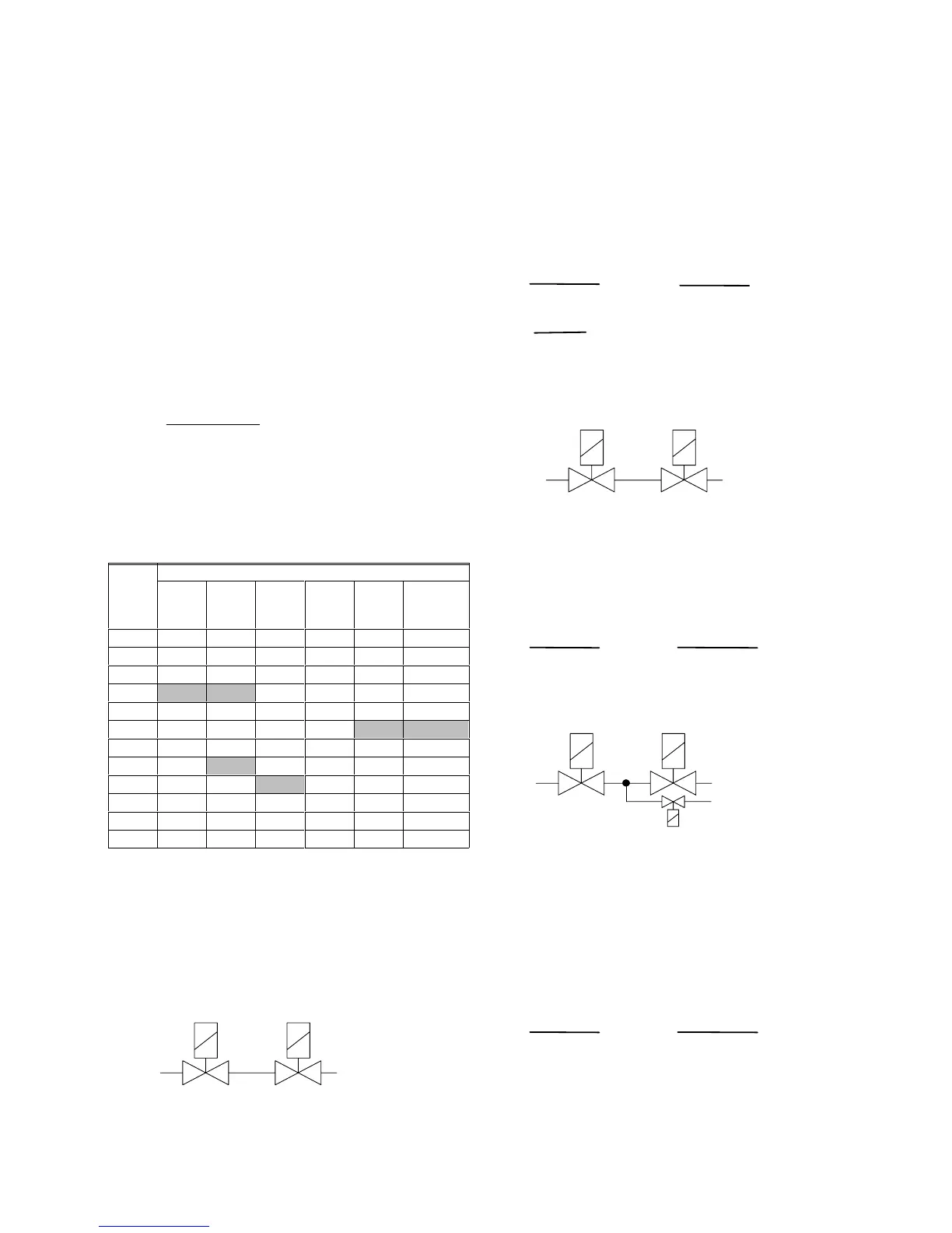
Calculation examples
Example 1
Calculate the maximum pipe length between two 1 1/2” safety
valves when an A4021A valve proving system is used with a
test period (per valve) of 25 seconds.
Given: Pi = 75 mbar
Qm = 30 dm
3
/h
valve: 1 1/2”→DN40
To be calculated: L(max.) [m]
Calculation:
p ≡
2xPixVp
Qm
[s]
→
Tp ≡
2x150x4.4
60
=22[s]
Choose always a A40121 with a test time (per valve) higher
than the (minimum) calculated test time Tp.
Example 3
Calculate the test period (per valve) in given situation.
Given: Pi = 150 mbar
Qm = 100 dm
3
/h
valve: VE4080A with 1 meter pipe (L1)
pilotvalve:VE4025with0.5meterpipe(L2)
To be calculated: Tp [s]
Calculation:
From Table 4. :
DN80T, L1=1m
DN25T, L2=0.5
Vp = V
1m + (
V
0.5m --
V
0m =
7.9 + (0.44 -- 0.19/2) = 8.25 dm
3
.
 Loading...