13
EN2R--9023 9705R0--NE
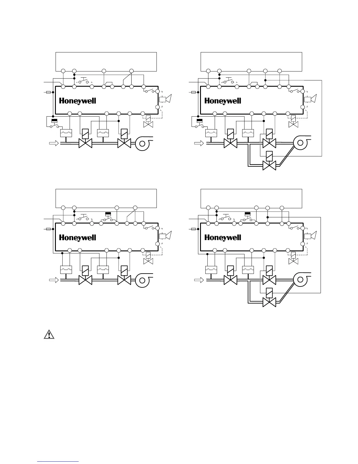
GENERAL WIRING DIAGRAMS
LGPS GPS
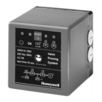
Valve Proving System
A4021A
6(N)
V2
8
10
ALARM
vent--valve
11
13
15
Ignition controller
4(N)
N L
1
2
T
(ext.)
1214
heat--demand
input
7
9
main--valve
output
V1
16 5(N)
reset
fuse
3
L
N
16A
Fig. 10. Wiring diagram for 2--valve configuration
pre--configuration
LGPS GPS
Valve Proving System
A4021A
6(N)
V2
8
10
ALARM
vent--valve
11
13
Ignition controller
4(N)
N L
1
2
(ext.)
1214
heat--demand
input
9
15 7
main--valve
output
V1
16 5(N)
reset
fuse
3
L
N
16A
T
Fig. 11. Wiring diagram 2--valve configuration for
post--configuration
LGPS GPS
Valve Proving System
A4021A
6(N)
V2
8
10
ALARM
vent--valve
11
13
Ignition controller
4(N)
N L
1
2
T
(ext.)
1214
heat--demand
input
9
15
main
output
V1
16 5(N)
reset
fuse
3
L
N
16A
Vp
7
pilot
output
valve
valve
Fig. 12. wiring diagram 3--valve configuration
(pre--configuration)
LGPS GPS
Valve Proving System
A4021A
6(N)
V2
8
10
ALARM
vent--valve
11
13
Ignition controller
4(N)
N L
1
2
(ext.)
heat--demand
input
9
V1
16 5(N)
reset
fuse
3
L
N
16A
Vp
1214
T
15
main
7
pilot
output
valve
valve
output
Fig. 13. Wiring diagram 3--valve configuration
(post--configuration)
WARNING
These are general wiring diagram and have not been
approved yet by an official approval body. Depending
on the application and used ignition controller special
wiring diagrams maybe required.
 Loading...