5
EN2R--9023 9705R0--NE
stabilization
time (3 sec.)
pressure
=low?
open valve 2
(5 sec.)
wait
(22 sec.)
open valve 1
(5 sec.)
pressure
=low?
stabilization
time (3 sec.)
pressure
=high?
wait
(22 sec.)
pressure
=high?
enable
ignition
controller
error + lock--out
no
no
no
no
yes
yes
yes
yes
test valve 1
test valve 2
self test
=OK?
yes
no
manual reset
1
2
3
4
5
6
7
8
10
11
12
13
pin 12
connected
enable
ignition
controller
yes
?
self test
=OK?
each 4 hours
no
no
yes
14
15
15
STANDBY
RUN
0
9
start
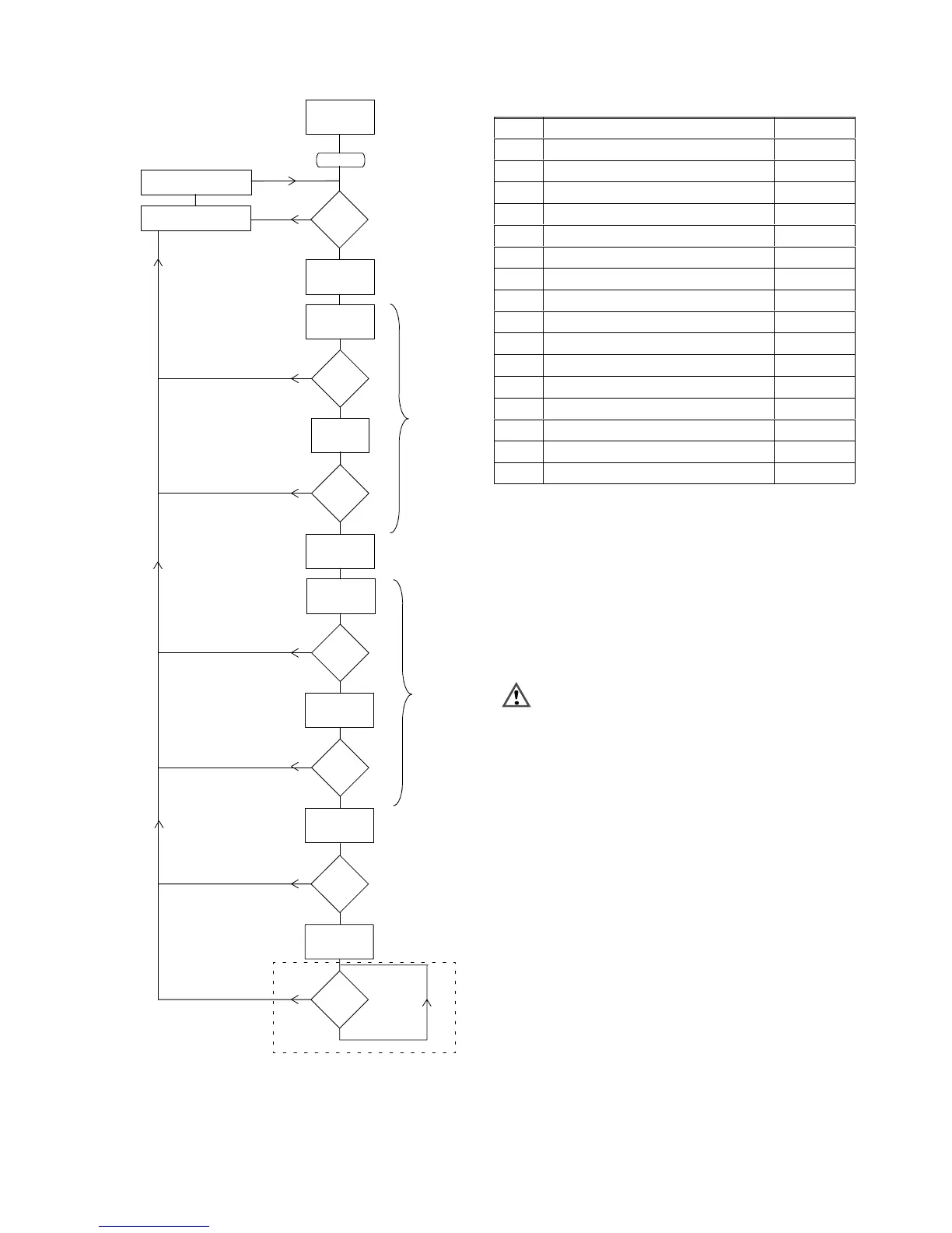
Fig. 5. General flow chart valve proving (given timings
for A4021A1002/1010
Table 2. Sequence timings for normal operation
State
Description Time
1)
(s)
0 STANBY infinite
2)
1 self--test + memory test <2
2 V2 powered 5
3 waiting for pressure to get low 3
4 wait 22
5 valve 1 powered 5
6 waiting for pressure to get high 3
7 wait 22
8 waiting for ignition controller to start indefinite
3)
9 RUN period, every 4 hours self--test
10 alarm, “error during test valve 1” indefinite
11 alarm, “valve 1 failing/leaking”
5)
indefinite
12 alarm, “error during test valve 2” indefinite
13 alarm, “valve 2 failing/leaking”
5)
indefinite
14 alarm, “error heat demand” indefinite
15 alarm, “self--test error”
4)
indefinite
1)
Timings depending on O.S. numbers, shown
A4021A1002/1010
2)
STANDBY can be infinite time period
3)
Depending on pre--purge and start--up time of the used
ignition controller
4)
When during the test sequence a fault is discovered by the
A4021, the system will go into a non--volatile lock--out and
generate an alarm “self test error” (see also
Troubleshooting section).The “self test error” also occurs
when the anti--recycle--counter reaches the value 10, see
also page 10 of the Product handbook.
5)
Leakage ≥ 0.1 % of maximum flow rate.
WARNING
No standard valve proving after lock--out of the
ignition controller.
Valve proving after lockout maybe required, this can
be achieved by special wiring diagrams. E.g. when a
DTSP switch is used to reset the ignition controller
and interrupting the heat--demand for the A4021A.
 Loading...