ac,
depending on O.S. number)
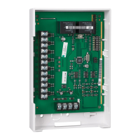
1 NO NO input Normally Open contact of the pressure
switch (high pressure)
n.a.
2 RESET RESET input Input for external reset connect with
momentary switch to line
n.a.
3 LINE LINE power--input Line voltage input for valve proving
system.
n.a.
4 N N power--input Neutral input for valve proving system. n.a.
5 N N power Neutral for external devices. n.a.
6 N N power Neutral for external devices. n.a.
7 V2--IN V2--IN input Valve--2 voltage from ignition controller n.a.
8 V2--OUT V2--OUT output Output connect with Valve--2 4A
9 HD LGPS input Heat--demand input (pre--configuration)
or LGPS input (post--configuration)
n.a.
10 ALARM ALARM input Alarm input 4A
11 ALARM ALARM output Alarm output 2A
12 RB RB input Read back signal for: heat--demand
(post-- config.) ign. contr. (pre--config.)
4A
13 VENT VENT output Normally open valve output 1A
14 IGNCTR HD output Heat call signal to ignition controller,
when there is a heat call and the valve
proving has taken place
4A
15 V1--IN V1--IN input Valve--1 voltage from ignition controller 2A
16 V1--OUT V1--OUT output Output connect with Valve--1 4A
NOTE: cos. ϕ = 0.7 for all outputs
 Loading...