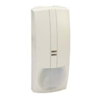
PRODUCT DESCRIPTION
The Activ8 PIR detect
or uses a special
designed optical Lens with unique Quad
(Four element) PIR Sensor and new ASIC
based electronics optimized
to eliminate false
alarms, caused by small animals and Pets.
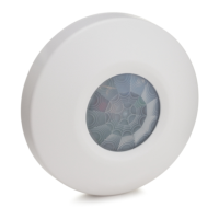
8IR103
PIR MOTION DETECTOR
With PET IMMUNITY up to 25Kg
INSTALLATION INSTRUCTIONS
English
P/N 7101507 REV. B A.Y.
The Activ8 PIR provides unprecedented
levels of immunity ag
ainst visible light.
The Detector offers an exceptional level of
detection capability and stability for every
security installation.
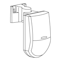
The Activ8 PIR is supplied with Wide Angle
lens.
The Activ8 PIR provides Pet immunity up
to 25Kg (55 lbs). For better immunity
avoid installation in areas where pets can
reach upwards.
Activ8 PIR FEATURES
DETECTION PATTERN
TYPICAL INSTALLATION
SELECT MOUNTING LOCATION
FEATURES
Choose a location most likely to intercept an
intruder. See detection pattern. The Quad high
quality sensor detects
motion crossing the beam;
it is less sensitive det
ecting motion towards the
detector.
Quad Linear Imaging Technology for
sharp analysis of body dimensions and
differentiation from background and
animals.
New ASIC based electronics.
The Activ8 PIR performs best when provided
with a constant and stable environment.
Immunity to animals up to 25kg (55 lbs).
18m Detection Range with Wide Angle
Lens.
AVOID THE FOLLOWING LOCATIONS
Temperature compensation.
Facing direct sunlight.
Compact Design for Residential
Installation.
Facing areas subject to rapid
temperature changes.
Variable pulse width adjustment.
Areas with air ducts
or substantial air
flows.
Sensitivity adjustment.
Environmental immunity.
Height installation calibration
free (1.8m – 2.4m).
LED Remote function.
REMOVAL OF FRONT COVER
MOUNTING THE DETECTOR
1. To remove the front cover, unscrew the holding
screw and gently raise the front cover.
KNOCKOUT HOLES
2. To remove the PC board, carefully unscrew the
holding screw located on the PC board.
3. Break out the des
ired holes for proper
installation.
4. The circular and rectangul
ar indentations at the
bottom base are the kno
ckout holes for wire
entry. You may also us
e mounting holes that
are not in use for running the wiring into the
detector.(For option with bracket - lead wire
through the bracket)
5. Mount the detec
tor base to the wall, corner or
ceiling. (For option with
bracket install bracket).
6. Reinstall the PC board by fully tightening the
holding screw. Connect wire
to terminal block.
7. Replace the cover by inserting it back in the
appropriate closing pins and screw in the holding
screw.
A. Wire access
holes
A
A
D
B. Use for flat
wall
mounting
A
B
C
C
B
C. Corner
mounting -
use all 4
holes. Sharp
left or right
angle
mounting -
use 2 holes
(top and
bottom)
C C
B
B
D. For bracket
mounting
Unscrew the holding
screw and open base
DETECTOR INSTALLATION
PCB LAYOUT
TERMINAL BLOCK CONNECTIONS
Terminals 4 & 5 - Marked
RELAY
These are the output re
lay contacts of the
detector. Connect to a
normally closed zone in
the control panel.
Terminal 7 - Marked + (+12V)
Terminals 1 & 6 - Marked EOL
End of line
option.
Connect to a positive Vo
ltage output of 8.2 -
16Vdc source (usually
from the alarm control
unit)
Terminals 2 & 3 - Marked TAMPER
If a Tamper function is
required connect these
terminals to a 24-hour normally closed protective
zone in the control unit. If the front cover of the
detector is opened, an immediate alarm signal will
be sent to the control unit.
Terminal 8 - Marked - (GND)
Connect to the negative
Voltage output or ground
of the control panel.