8
Connections to the Accord
Mounting and Wiring the LED Remote Keypad
To mount and wire the Accord LED keypad:
1. Press down the two base clips recessed on
top of the keypad while gently pulling the two
halves of the case apart.
2. Route the wiring from the Control Panel
through the Cable Entry Hole on the back
case. Use Knockout Holes A or B if
alternative routes are necessary. Tip: Use a
knife to help dislodge knockouts.
3. Securely mount the back case to a wall or
electrical box via the mounting holes. Ensure
The Tamper Tab is securely screwed down.
4. The remote keypad PCB should be wired to
the control panel PCB as outlined in Table
2.1 LED Keypad Wiring.
5. Re-attach the keypad front to the back case
by inserting the hinges on the keypad front
into the hinge retainers on the bottom of the
keypad back case. Gently apply pressure to
the keypad front until the two retaining tabs
click firmly into place.
Table 2.1 LED Keypad Wiring.
Note: The keypad voltage should be at least 12.5V
Keypads can be wired to the control panel independently, in series, or in a star
configuration. Up to four keypads can be connected.
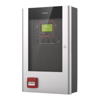
Fig 2.3 Accord LED Keypad
Cable Entry
Hole
Knockout
Hole A
Knockout
Hole B
Hinge Slot
Hinge Slot
Mounting Holes
Mounting Holes
Tamper Tab
Screw Hole
Base Clip
Base Clip
lenaPdapyeK
+xuAev+
–xuAev–
DAP'Kdapk

 Loading...