C7061A,F DYNAMIC SELF-CHECK ULTRAVIOLET FLAME DETECTOR
11 65-0223—07
Replacing Ultraviolet Sensing Tube
(All Models) (Fig. 11)
IMPORTANT
Be very careful not to kink or otherwise damage the
flexible shutter.
1. Open the master switch and remove the cover from the
detector (see instructions above).
2. Locate the UV sensing tube.
3. Gently bend the alignment guide just enough to free the
tip of the tube.
4. Insert a screwdriver between the tube base and the
socket, and gently pry the tube out of its socket.
5. Pull the tube completely out of its socket.
6. Insert the new tube through the openings in the shutter
assembly.
7. Align the three pins on the new tube with the holes in the
socket.
8. Carefully push the new tube firmly into the socket until
the alignment guide snaps into place around the tip of
the tube.
9. Make sure the new UV sensor tube is seated securely.
10. Replace the detector cover.
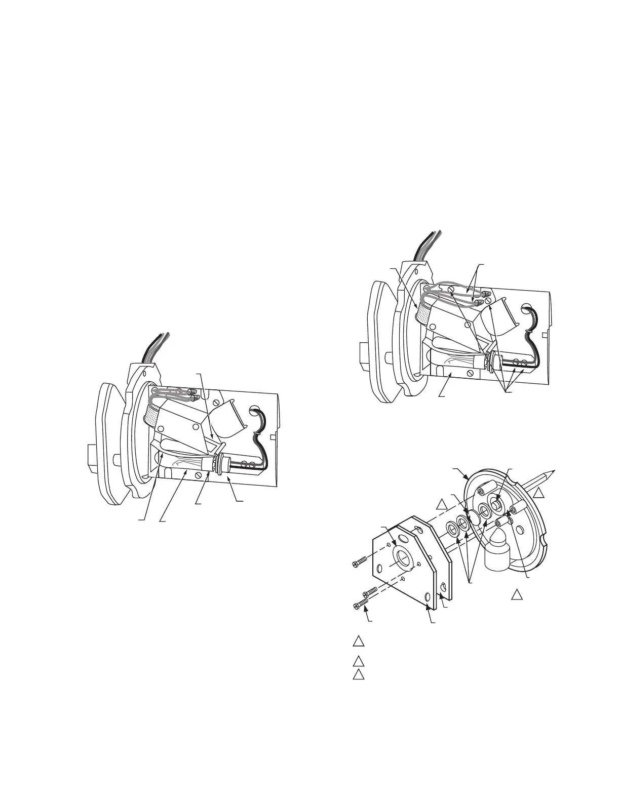
Fig. 12. Replacing ultraviolet radiation sensing tube.
Replacing Coil and Shutter Assembly
(Fig. 12)
NOTE: Use only a 190971B Coil and Shutter Assembly.
1. Open the master switch and remove the detector cover
(see Removing Detector Cover section).
2. Remove the ultraviolet sensing tube (steps 1 through 5
of Replacing Ultraviolet Sensing Tube section).
3. Cut the white wires as close as possible to the crimped
connectors, and remove the crimped connectors.
4. Remove the three mounting screws from the base of the
coil and shutter assembly. Put the screws in a safe
place.
5. Remove the coil and shutter assembly.
6. Install the new coil and shutter assembly.
IMPORTANT
Be very careful not to kink or otherwise damage the
flexible shutter.
7. Insert the three mounting screws into the base of the coil
and shutter assembly and tighten securely.
8. Remove sufficient insulation from each of the two white
leadwires remaining on the detector, and also from each
of the two white leadwires on the new coil.
9. Using solderless connectors, connect one of the coil
wires to one of the remaining white leadwires. Connect
the other coil wire to the other remaining white leadwire.
10. Reinstall the sensing tube (steps F through I of
Replacing Ultraviolet Sensing Tube section).
11. Replace the detector cover.
Fig. 13. Replacing coil and shutter assembly.
Fig. 14. Replacing quartz viewing
window or focusing lens.
FLEXIBLE
SHUTTER
TUBE
BASE
ULTRAVIOLET
SENSING TUBE
SHUTTER
ASSEMBLY
TUBE
SOCKET
M10141
SHUTTER
ASSEMBLY BASE
MOUNTING
SCREWS (4)
M10142
COIL
COIL
CONNECTING
WIRES
PENCIL
1
VIEWING WINDOW CAN BE REPLACED WITH EITHER SIDE TOWARD
THE FLAME.
ONLY ONE GASKET ON EACH SIDE OF THE FOCUSING LENS.
REMOVE THE THREE MOUNTING SCREWS AND MOVE THE COIL
AND SHUTTER ASSEMBLY OUT OF THE WAY TO PUSH OUT THE
VIEWING WINDOW.
3
114372 (20 PSI) OR 122748 (50 PSI)
QUARTZ VIEWING WINDOW (OR 124204
QUARTZ FOCUSING LENS, 20 PSI)
FACEPLATE
1
2
RED RUBBER WASHER
(BETWEEN
GASKET AND
FLANGE)
114465 RUBBER
MOUNTING
GASKETS (3)
WINDOW
APERTURE
BACK SECTION OF
MOUNTING FLANGE
120739 FIBER-NEOPRENE GASKET
MOUNTING
SCREWS (3)
2
3
M10130
 Loading...