C7061A,F DYNAMIC SELF-CHECK ULTRAVIOLET FLAME DETECTOR
7 65-0223—07
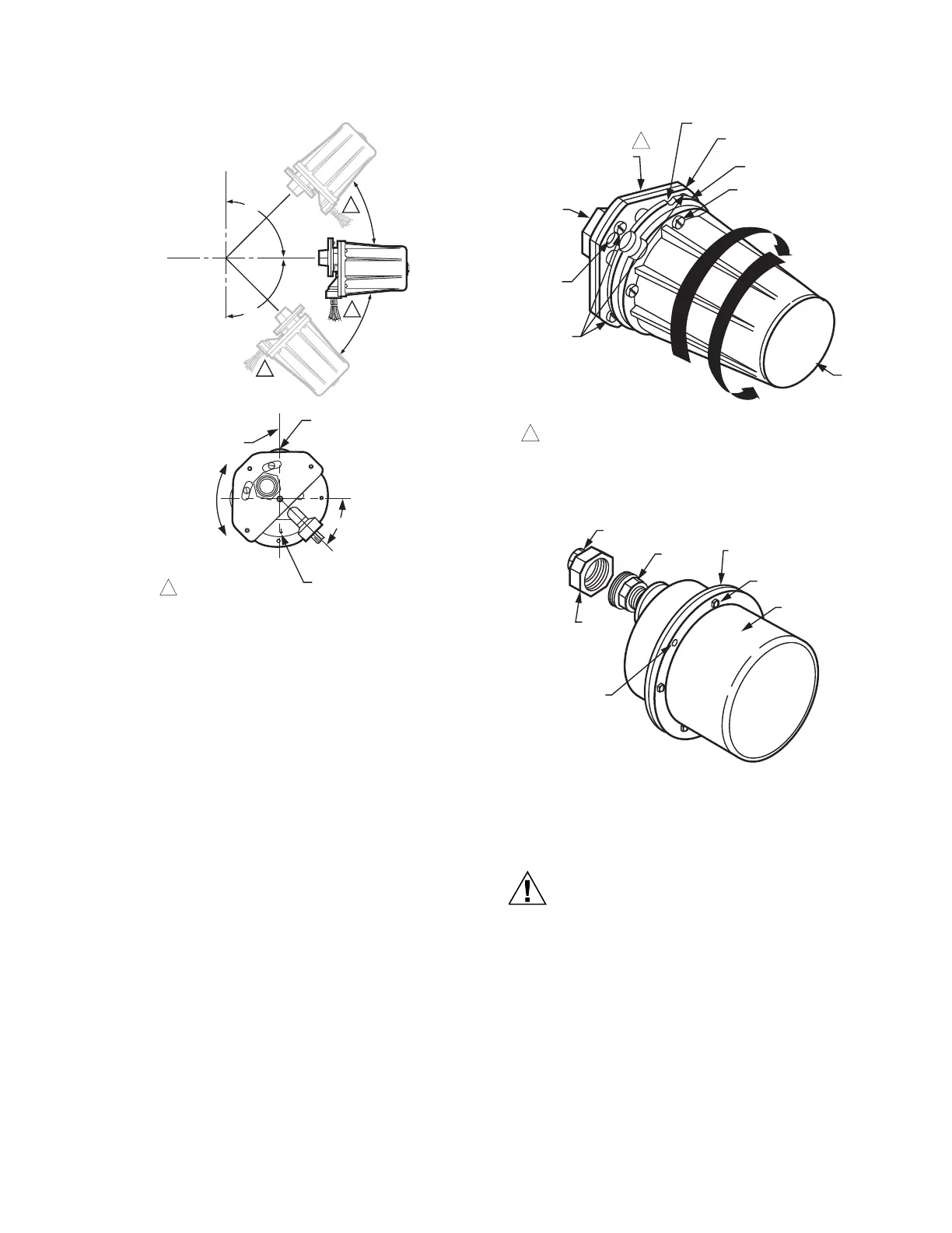
Fig. 7. C7061 mounting positions.
IMPORTANT
The notch and arrow on the faceplate must be aligned
in a vertical plane with the notch up and the arrow
pointing down.
The housing must be mounted with the conduit opening
approximately 45¡ below horizontal (see Fig. 6).
To mount a C7061A (Fig. 8):
1. The mounting flange is in two pieces. Loosen (but do not
remove) the three screws holding the flange together.
2. Slightly rotate the detector so the slots in the back
section of the mounting flange clear the screws in the
front section; then separate the two sections.
3. Screw the front section of the mounting flange onto the
sight pipe, reducer, or other fitting.
4. Fit the slots in the back section of the mounting flange
(with the detector) over the three screws in the front sec-
tion, and rotate the detector so the screws hold the
flange together.
5. Tighten the screws securely.
To mount the C7061F with explosion-proof housing (Fig. 9):
1. Unscrew the collar on the pipe union and remove the
coupling section. The collar and coupling are in two
pieces; do not separate them.
2. Screw the coupling onto the sight pipe, reducer, or other
fitting.
3. Mount the remainder of the pipe union (with the detector)
onto the coupling and securely tighten the collar.
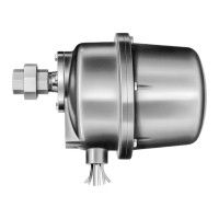
Fig. 8. Mounting C7061A Detector.
Fig. 9. Mounting a C7061F Detector.
WIRING (FIG. 10)
Equipment damage hazard.
Improper wiring can permanently damage
amplifier.
When using a C7061A with an R7861 Dynamic
Self-Check Amplifier, be careful not to short the white
shutter leadwires together (by wiring incorrectly,
leaving an incorrect jumper wire, or stripping the
insulation too much so the bare leadwires can touch).
1. All wiring must comply with applicable local electrical
codes, ordinances, and regulations. Use NEC Class 1
wiring.
2. Keep the flame signal leadwires as short as possible
from the flame detector to the terminal strip or wiring
subbase. Capacitance increases with leadwire length,
reducing the signal strength. The maximum permissible
leadwire length depends on the type of leadwire and
HORIZONTAL
PLANE
VERTICAL
PLANE
90
90
1
1
1
NOTCH IN FACEPLATE
MUST BE UP
HORIZONTAL
PLANE
NOTCH AND ARROW
MUST ALWAYS BE
ALIGNED IN A
VERTICAL PLANE
C7061A
MUST NOT
BE ROTATED
AROUND
ITS AXIS
ARROW ON FACEPLATE
MUST BE POINTING
DOWN
45
ADE IN U.S.A.
MOUNT WITH
ARROW DOWN
1
NOTE DOWNWARD
POSITIONING OF
CONDUIT OPENING.
M10127A
COVER
M24026
ROTATE DETECTOR
THIS WAY WHEN MOUNTING
ROTATE DETECTOR
THIS WAY TO
SEPARATE
MOUNTING
FLANGE
CAPTIVE COVER SCREW (4)
FACEPLATE
BACK SECTION OF
MOUNTING FLANGE
NOTCH IN FACE PLATE
124198 (1 IN. NPT)
FRONT SECTION OF
MOUNTING FLANGE
SCREW ONTO
SIGHT
PIPE
SLOT(3)
FLANGE
SCREWS (3)
1
1
C7061A1046: 124198 (1 INCH NPT) FRONT SECTION OF
MOUNTING FLANGE.
SCREW COUPLING
ONTO SIGHT PIPE
PIPE
UNION
COLLAR
HOLE
KEYED
TO PIN
ON BODY
FLANGE
BODY FLANGE
HEX-HEAD
COVER BOLT (6)
COVER
M1955
 Loading...