SOLID STATE ECONOMIZER SYSTEM
63-2484—1
19
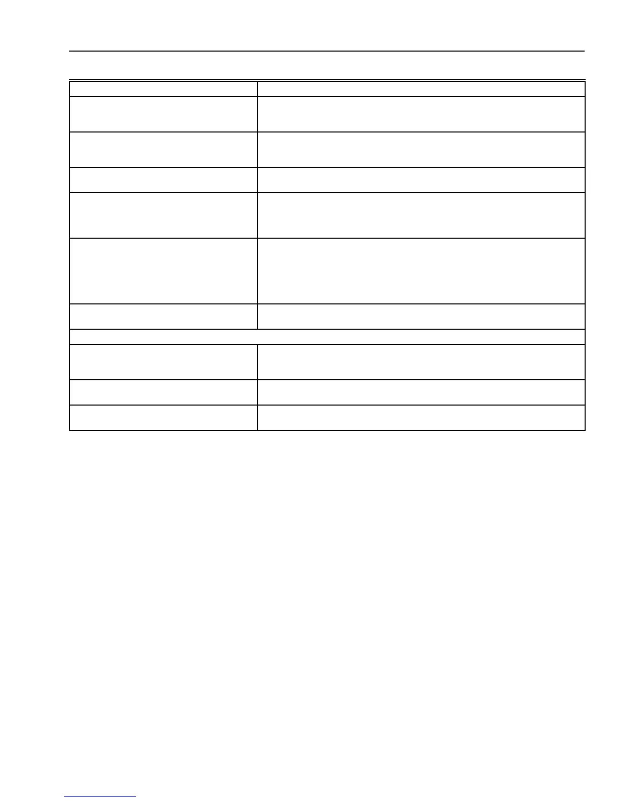
Table 8. Troubleshooting three-position economizer—outdoor enthalpy above setpoint.
NOTES:
1. Standard economizer position based on enthalpy control set on the A setting and 50 percent relative humidity.
2. Closed position is either the minimum position or fully closed, depending on the job setting.
3. Opening/closing is dependent on the mixed air temperature.
Condition on Logic Module Should Be Conditions Not Met
1. Red LED not lighted. 1. If the LED glows, the module thinks it is in the economizer mode. Verify
the conditions are above the enthalpy setpoint, see Note 2. Check wiring
to Enthalpy Control for a short from {SO} and {+}.
2. 24 Vac to terminals {TR} and {TR1}, {X}
and {TR}.
2. Check the wiring from [G] and [C] on the unit low voltage terminal strip.
{TR} and {TR1} power the actuator. {X} and {TR} provide power for
minimum position.
3. 24 Vac to terminals {1} and {TR}. 3. Verify that there is a call for cooling from the thermostat. Without a call for
cooling the compressor can not be in the normal air conditioning mode.
4. 24 Vac to terminals {2} and {TR}. 4. If 24 Vac is not on {2} and {TR}, the internal contacts are not set correctly.
Remove the {SO} wire from the module. If 24 Vac is on {2} and {TR}, the
enthalpy control is bad or the {SO} and + wiring are shorted together. If no
voltage to {2} and {TR}, the module is bad.
5. Continuity on terminals {1} and {2}, {3}
and {4}.
5. If there is not continuity for {1} to {2}, the internal contacts are not in the
correct position, and either the module or the enthalpy control is defective.
If there is continuity from terminals {1} and {2}, the red LED should not be
lighted. If there is continuity and the LED glows, the module is defective. If
there is continuity on terminals {3} and {5}, the internal contacts are
correctly energized. Damper motor should be in the economizer mode.
6. Compressor does not operate with all
above conditions correct.
6. Check the wiring from {2} to Y1 on the unit low voltage control board.
Verify that there are not 24 Vac to Y1 and C on the unit.
Second Stage
7. 24 Vac to terminals {3} and {TR}. 7. Verify that the thermostat is two-stage. Check for a call for a second stage
cooling. If there are not 24 Vac on {3} and {TR}, check wiring from Y2 on
the thermostat to the module.
8. 24 Vac to terminals {5} and {TR}. 8. If {4} and {TR} do not have 24 Vac and {3} and {TR} have 24 Vac, the
internal switch 1S is not in the correct position. The module is defective.
9. Compressor does not operate with
second stage conditions met.
9. If all other functions are correct, check the wiring from {4} to Y2 on the unit
low voltage terminal board.
{ } Terminals on the logic module.
[ ] Low voltage input from unit or thermostat.
 Loading...


