SOLID STATE ECONOMIZER SYSTEM
63-2484—1
20
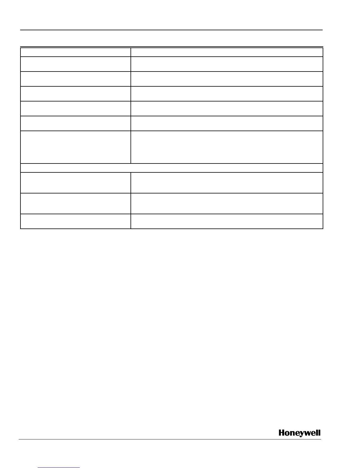
Table 9. Troubleshooting three position economizer—outdoor enthalpy below setpoint.
NOTES:
1. Standard economizer position based on enthalpy control set on the A setting and 50 percent relative humidity.
2. Closed position is either the minimum position or fully closed, depending on the job setting.
3. Opening/closing is dependent on the mixed air temperature.
Condition on Logic Module Should Be Conditions Not Met
1. Red LED lighted. 1. Jumper terminals {SO} and {+}. If the LED glows, the module is okay, see
Note 2. Check wiring to enthalpy control.
2. 24 Vac to terminals {TR} and {TR1}. 2. Check the wiring from [G] and [C] on the unit low voltage terminal strip.
{TR} and {TR1} power the actuator.
3. 24 Vac to terminals {1} and {TR1}. 3. Verify there is a call for cooling from the thermostat. Without a call for
cooling, the motor can not be in the economizer mode.
4. No continuity on terminals {1} and {2}. 4. If there is continuity from terminals {1} and {2}, then the red LED cannot be
lighted. If there is continuity and the LED glows, the module is defective.
5. Continuity on terminals {3} and {5}. 5. If there is continuity on terminals {3} and {5}, the internal switch 1S is
correctly energized. Damper motor should be in a modulating mode.
6. Motor does not operate with all above
conditions met.
6. Jumper the mixed air sensor terminals {6} and {D}. If the motor begins to
operate, check the wiring to the sensor. If it is correct, the temperature is
below the sensor setpoint or the sensor is defective. If the motor does not
operate, the wiring is correct, and the temperature is above the sensor
setpoint, the motor is bad.
Second Stage
7. 24 Vac to terminals {3} and {TR}. 7. Verify that the thermostat is two-stage. Check for a call for a second stage
cooling. If 24 Vac is not on {3} and {TR}, check wiring from Y2 on the
thermostat to the module.
8. 24 Vac to terminals {5} and {TR}. 8. If {5} and {TR} do not have 24 Vac, and {3} and {TR} do have 24 Vac, then
the internal switch 1S is not in the correct position. The module is
defective.
9. Compressor does not operate with
second stage conditions met.
9. If all other functions are correct, check the wiring from {5} to Y2 on the unit
low voltage terminal board.
{ } Terminals on the logic module.
[ ] Low voltage input from unit or thermostat.
Honeywell Europe S.A.
3 Avenue du Bourget
B-1140 Brussels Belgium
Honeywell Asia Pacific Inc.
Room 3213-3225
Sun Hung Kai Centre
No. 30 Harbour Road
Wanchai
Hong Kong
Home and Building Control
Honeywell Limited-Honeywell Limitée
155 Gordon Baker Road
North York, Ontario
M2H 2C9
Honeywell Latin American Division
Miami Lakes Headquarters
14505 Commerce Way Suite 500
Miami Lakes FL 33016
Helping You Control Your World
®
63-2484—1 G.R. Rev. 1-97 Printed in U.S.A.
Home and Building Control
Honeywell Inc.
Honeywell Plaza
P.O. Box 524
Minneapolis MN 55408-0524
www.honeywell.com/building/components
 Loading...


