Do you have a question about the Honeywell 5701 and is the answer not in the manual?
Key features of the 5701 Series Control System, including channel capacity and input types.
Describes the physical construction, rack widths, and component layout of the system.
Overview of the microprocessor-based 5701 Series Control System for gas detection.
Details the four standard rack configurations and their internal structure.
Describes the two wall-mounted cabinets used to house the system racks.
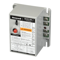
Explains the functionality, types, and front panel layout of the 5701 Single Channel Control Card.
Details the interface cards and various relay cards for connecting sensors and outputs.
Describes the Engineering Card's role in system configuration, maintenance, and status indication.
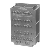
Explains the DC Input Card's function for power distribution and isolation.
Details the types, upgrades, and connections for AC to DC power supply units.
Describes the blank panels used to fill unused single channel control card spaces.
Introduces operational and engineering facilities for gas detection system maintenance.
Details the front panel layout and subdivisions of the Single Channel Control Card.
Explains the Engineering Card's function and LED indicators for status.
Summarizes the System 57 controller installation procedures.
Instructions for unpacking and checking the received equipment for damage or deficiencies.
Guidelines for installing the control system in a safe and suitable area with adequate ventilation.
Specifies requirements for routing, screening, and resistance of sensor and power cables.
Details how to calculate the system's total power requirement based on components.
Discusses thermal planning and ventilation requirements for the system to prevent overheating.
Ensures compatibility of control cards, sensors, and power supply units with system requirements.
Step-by-step guide for securing cabinets and installing racks and power supplies.
Instructions for cutting apertures and installing racks into panels according to dimensions.
Details how to mount racks into standard 19" mounting frames securely.
Provides general guidelines, placement, and line resistance considerations for sensor installation.
Explains how to set configuration links for sensor drive modules on control cards.
Describes specific wiring connections for various sensor types to interface/relay cards.
Details relay output configurations and analogue output connections.
Explains configuration of remote reset and inhibit inputs for control cards.
Details connection methods for site DC supply and battery backup to the DC Input Card.
Describes AC/DC power supply unit connections, wiring, and grounding.
Instructions for upgrading power supply units to higher wattage by adding modules.
Guide for commissioning and maintenance with a single power supply connection.
Step-by-step procedure for safely starting up the system and checking voltages.
Procedures for sensor calibration, including zero and span adjustments.
Annual checks and general maintenance procedures for system integrity and cleanliness.
Lists and explains system error codes, their meanings, causes, and fault signals.
Provides a guide to diagnosing and resolving common system faults based on indicators.
Introduces operating instructions for general system use without the Engineering Key.
Outlines user-accessible operations like channel reset, select, and view alarms.
Details basic control card operations like reset, select, and deselect using the front panel.
Explains how to use Engineering Card functions for viewing data and settings without the key.
Introduces engineer-specific functions unlocked by the Engineering Key for system setup.
Lists engineering tasks like channel inhibit, calibration, and monitoring accessible via Engineering Card.
Procedure for unlocking the Engineering Card using the Engineering Key.
Describes how to manipulate values and confirm settings using card push-buttons.
Explains how to enable/disable channel inhibit locally or remotely.
Details setting alarm thresholds and performing relay tests for system alarms.
Procedure for adjusting the bridge current for catalytic sensors.
Steps for performing zero signal calibration on sensors in a gas-free atmosphere.
Steps for performing span signal calibration on sensors using span gas.
Specific procedure for initial span calibration of new sensors.
How to monitor live sensor signal values (bridge voltage or loop current).
Procedure for setting the system's internal clock and calendar date.
Refers to maintenance procedures detailed in Chapter 6, Section 4.8.
Lists compliance standards and certifications for the system, including ATEX.
Specifies operating and storage temperature, and humidity limits.
Details RFI/EMC compliance standards and special conditions.
Details power consumption, DC, and AC power supply specifications.
Provides specifications for various system modules like interface/relay cards, control cards, etc.
Specifies material, weight, and gland entries for cabinet assemblies.
Lists components, material, and weight for different rack assemblies.
Details specifications for AC to DC power supply units, including dimensions and current.
Diagram showing part numbers for system components like control and relay cards.
Diagram showing part numbers for cabinets, racks, and power supply units.
| Brand | Honeywell |
|---|---|
| Model | 5701 |
| Category | Control Systems |
| Language | English |