2 - 26
MAN0443.P65 Issue 13 Aug 04 5701 Control System
05701-M-5001 A02279
CHAPTER 2 - SYSTEM DESCRIPTION
Connections to the Engineering
Card optional modules. Functions
vary depending upon type of
module fitted.
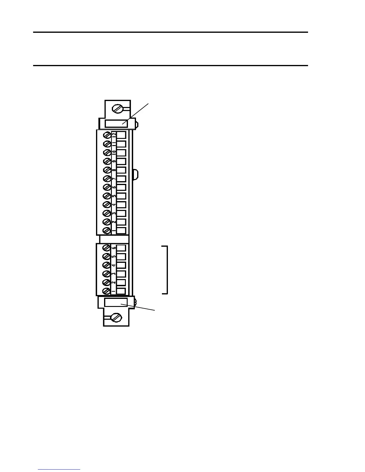
User Terminal Reference
Slot Location
TB1
12 +24V In (PSU 1)
11 0V In (PSU 1)
10 +24V In (PSU 2*) or +24V Out (PSU 1)
9 0V In (PSU 2) or 0V Out (PSU 1)
8 +24V In (AUX 1)
7 0V In (AUX 1)
6 +24V In (AUX 2*) or +24V Out (AUX 1)
5 0V In (AUX 2) or 0V Out (AUX 1)
4 +24V Out (Fused)
3 0V Out (Fused)
2 Ground
1 Ground
TB2
6
5
4
3
2
1
* PSU 1 and PSU 2 (and AUX 1 and AUX 2) must be
compatible with parallel connection.
7.2 Rear Access Connections
Note: For high integrity systems it is possible to connect the dc power
direct to individual relay cards.

 Loading...