MAN0443.P65 Issue 13 Aug 04 5701 Control System
05701-M-5001 A02279
CHAPTER 4 - INSTALLATION INSTRUCTIONS
4 - 21
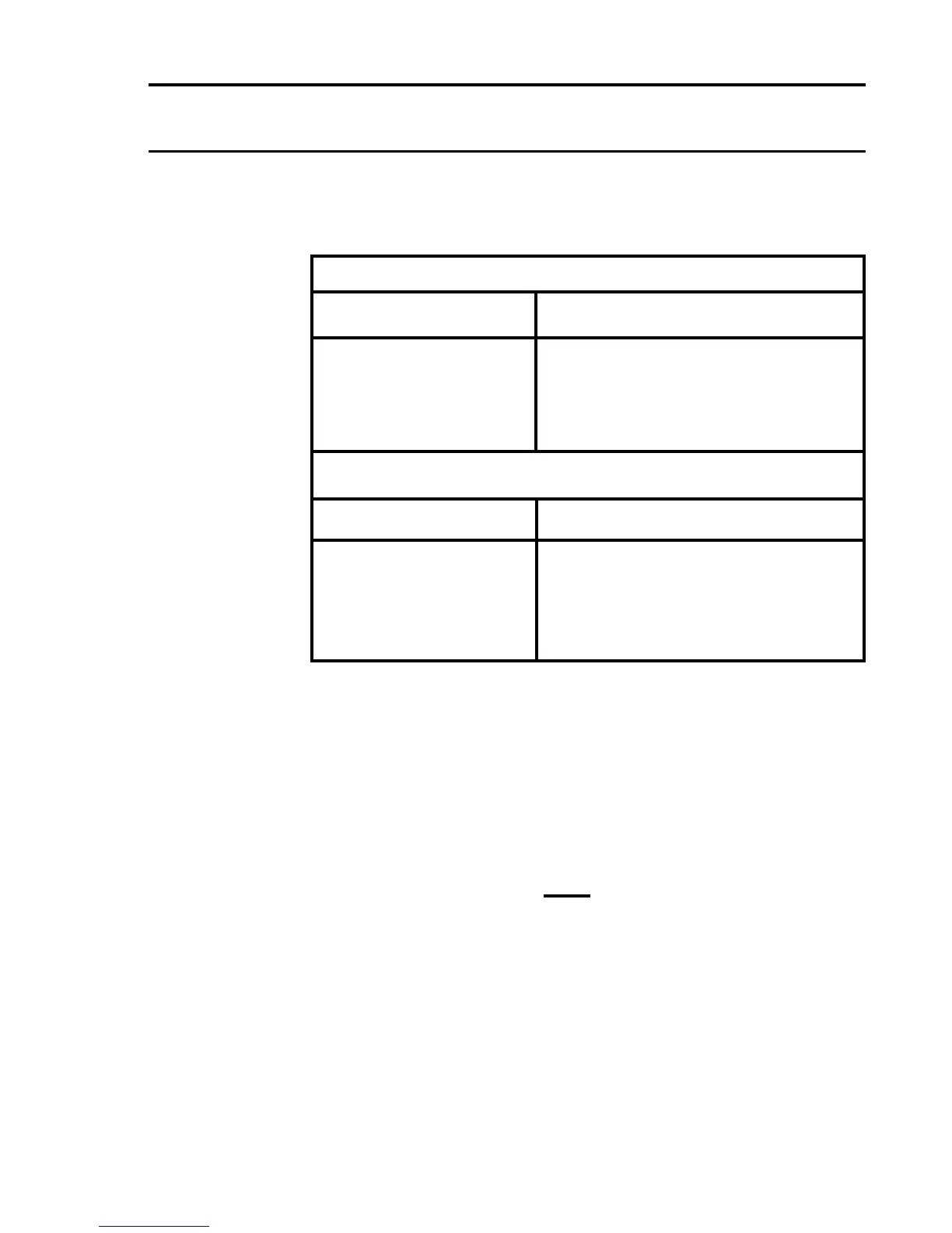
11.3 Cable Resistance Guide
A guide to the resistance of various copper cable sizes is given below:
Solid Copper Conductor
Cross Sectional Area (mm˝) Maximum resistance at 20°C (ohm/km)
0.50 38.0
0.75 25.3
1.00 19.0
1.50 12.6
2.50 7.6
Stranded Copper Conductor
Cross Sectional Area (mm˝) Maximum resistance at 20°C (ohm/km)
0.50 36.8
0.75 24.5
1.00 18.4
1.50 12.3
2.50 7.4
11.4 Catalytic Sensors
The maximum line resistance of cabling for a catalytic sensor varies
with the current and voltage requirements of the type of sensor installed.
It is also subject to a maximum of 10V permitted across terminals S
and NS at the Field Interface/Relay Card.
Maximum line loop resistance is calculated as follows:
10 - V
s
R
L
=
I
s
Where: R
L
= Total Line Resistance (ohms)
V
s
= Sensor Voltage (V)
I
s
= Sensor Current (A)

 Loading...